

- Описание AFS2
- Характеристики AFS2
- Инструкции
- Отзывы AFS2
- Похожие
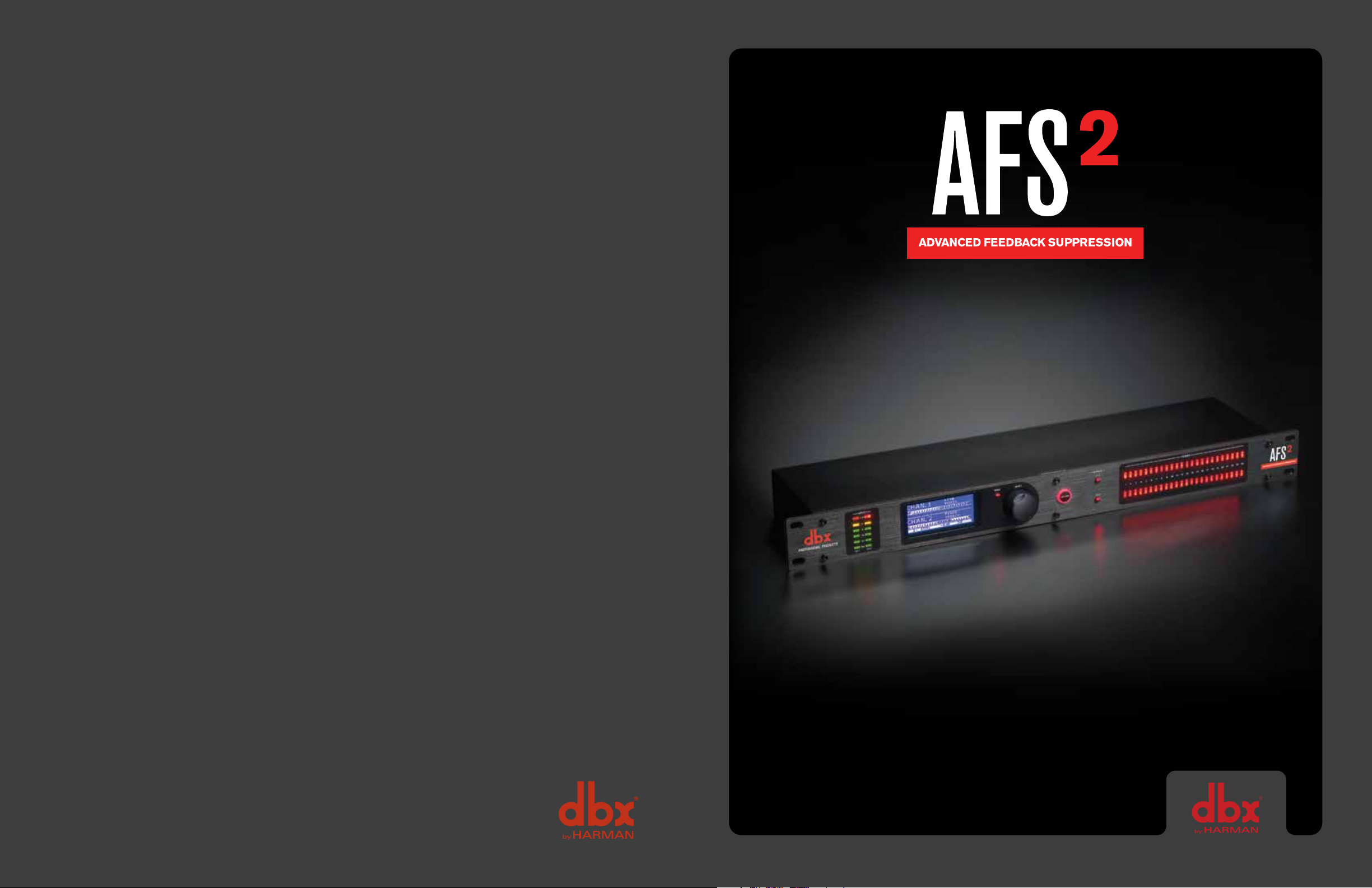
Подавитель обратной связи DBX AFS2
DBX AFS2 – это двухканальный процессор подавления обратной связи.
Устройство обеспечивает эффективное уменьшение обратной связи. В данном устройстве компания DBX использует свою запатентованную технологию AFS, которая ранее была доступна только в продуктах класса hi-end. Дополнительно к фильтрам подавления обратной связи, AFS2 также предлагает пользователю выбор разнообразных режимов работы, выбор фиксированного или скользящего фильтра, а также различных типов фильтрации, доступ к которым можно получить посредством удобного и интуитивно понятного пользовательского интерфейса.
Устройство DBX AFS2 предоставляет пользователю следующие функции и возможности:
запатентованная технология dbx Advanced Feedback Suppression (расширенное подавление обратной связи)
24 программируемых фильтра со светодиодными индикаторами на канал
стерео или моно обработка канала
режимы фиксированного и скользящего фильтра
выбор времени отключения фильтра
специализированные типы фильтров: речь, музыка, музыка/речь
пять сохраняемых пользовательских предустановок
измерение входного уровня
XLR и TRS электронно сбалансированные вход и выходы
порт USB для обновления прошивки устройства.
Ключевыми функциями AFS2 являются фиксированный и скользящий режимы работы, а также возможность отключения фильтра в нужный момент времени. Скользящий режим работы выполняет непрерывное обновление размещения фильтра, что обеспечивает гибкость работы. Функция отключения фильтра автоматически удаляет назначения фильтров, которые более не нужны, что позволяет сохранить целостность звука.
AFS позволяет пользователю оптимизировать уменьшение обратной связи. С помощью AFS обратная связь удаляется автоматически, а высокоточные фильтры срезают только нужную часть частотного спектра.
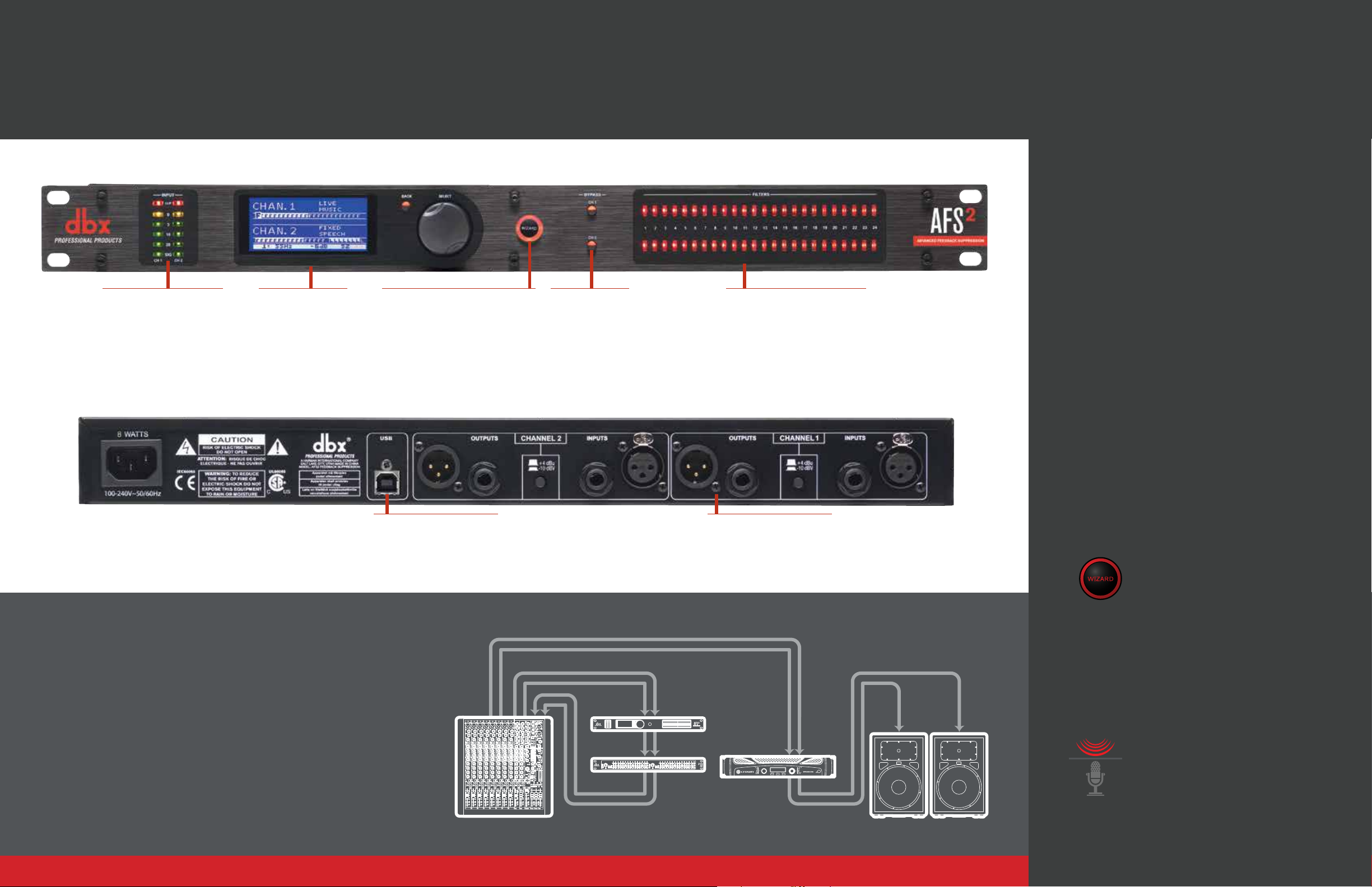
AFS 224 имеет симметричные входы и выходы, которые могут быть использованы с любым симметричным или несимметричным линейным устройством. Разъемы двух типов, XLR и 1/4\’\’, расположены на задней панели устройства. Также на задней панели расположен порт USB, разъем для подключения кабеля электропитания и переключатель рабочего уровня, который позволяет осуществлять выбор между номинальным рабочим уровнем +4 dBu или -10 dBV.
На передней панели устройства расположены элементы управления и индикации, в том числе LCD дисплей. Четыре светодиодных индикатора демонстрируют уровень входного сигнала. Диапазон индикаторов входного уровня — от -10 до +18 dBu. Еще один индикатор указывает на наличие ограничения входного сигнала. Однократное нажатие кнопки Bypass позволяет обойти узкополосный режекторный фильтр в траектории сигнала. Нажатие и удерживание этой кнопки используется для обнуления фильтров. Кнопка Type используется для выбора типа AFS и для связи Каналов А и В.
AFS2 предлагает несколько типов подавления обратной связи: Music/Speech, Speech, Music. Выбранный тип определяет ширину узкополосного режекторного фильтра, используемого для подавления обратной связи. В режиме «музыка» используются более узкие фильтры, минимизирующие эффект подавления, а в режиме «речь» — более широкие, позволяющие ускорить работу AFS2.
Производитель: dbx, Inc.. Эта американская компания была основана в 1971 году и добилась популярности в первую очередь благодаря своим системам шумоподавления. Сейчас является известным производителем профессионального оборудования для звукозаписи, входит в состав крупного объединения «Harman International Industries».
Технические характеристики:
Аналоговые входы:
Количество входов: 2
Разъемы: штепсельный XLR и 1/4” TRS
Тип : электронный симметричный/несимметричный, RF фильтрованный
Импеданс: Симметричный 50 КОм, Несимметричный 25 КОм
Максимальный линейный входной уровень: +20 dBu
CMRR: > 40 dB, обычно > 55dB @ 1 кГц
Аналоговые выходы:
Количество выходов: 2
Разъемы : штырьковый XLR и 1/4” TRS
Тип : электронный симметричный/несимметричный, RF фильтрованный
Импеданс: Симметричный > 120 Ом, несимметричный > 60 Ом
Максимальный выходной уровень: +20 dBu
A/D производительность:
Тип : dbx система преобразования Type IV
Динамический диапазон: >110 дБ A-взвешенный, >107 дБ невзвешенный
Type IV динамический диапазон: >119 дБ, A-взвешенный >117 дБ, невзвешенный
A/D Преобразование: 24 бит
D/A производительность:
Динамический диапазон: 112 дБ A-взвешенный, 109 дБ невзвешенный
D/A преобразование: 24 бит
Характеристики системы:
Частота дискретизации: 48 кГц
Динамический диапазон: >107 дБ A-взвешенный, >104 дБ невзвешенный
Гармонические искажения + шум: 0.0043 проц. Тип., при +4 dBu, 1 кГц
АЧХ: 20 Гц – 20 кГц, +/- 1.0 дБ
Межканальные перекрестные помехи: >100 дБ тип.
Перекрестные помехи от входа на выход: >100 дБ тип.
Прочие характеристики:
Рабочее напряжение: 100-240 В, 50/60 Гц
Потребляемая мощность: 8 Вт
Размеры (В х Г х Ш): 4,45 см х 14,92 см х 48,26 см
Вес: 2,04 кг
DBX AFS2 характеристики товара
DBX AFS2 инструкция на русском языке
На этот товар еще нет инструкций
Отзывы на DBX AFS2
©20 14 HAR MAN. dbx Professional Products is a registered
trademark of HARMAN. All features and specifications are
subject to change. All rights reserved.
Hear no evil
and see no evil.
The simplest way to eradicate feedback before it starts.
Hear no evil and see no evil.
dbx Professional Products set the standard
Input Signal Meters
Accurately monitor input signal
levels accurately with five
segment LEDs per channel
plus red clip LED indicator.
The AFS2, new and improved.
Easy-to-Read Display
Navigate menus, interact
with the AFS
easily manipulate settings
with the bright, legible,
interactive display.
2
Wizard, and
Wizard Functions
The AFS2 Feedback Suppression
Wizard makes setup easy and
approachable for users with varying
levels of technical know-how. Select
application-specific filter types for
Speech, Music Low, Music Medium, and
Music High, and the number of fixed or
live filters up to a total of 24.
Channel Bypass
Isolate problem
channels with
the option to bypass
Channels 1, 2, or both.
Notch Filter Indicators
Visually monitor the number of notch
filters applied on each channel.
for excellence in live audio feedback
suppression, but dbx engineers — always the
consummate and discerning authorities on
live sound — saw an opportunity to push
the technology further
The completely redesigned AFS2 now
offers a highly-intuitive Wizard function that
takes all of the guesswork out of setting up any
room, incorporates a completely redesigned
Advanced Feedback Suppression module, and
— perhaps best of all — now provides the user
with a full LCD display for setup and monitoring.
2
Invest in the AFS
Advanced Feedback
Suppression processor from dbx to
protect your ears and your audio equipment
from annoying and potentially damaging
USB Connection
Keep your firmware up-to-date.
Visit www.dbxpro.com for the
latest firmware updates.
Q: How do you kill feedback without killing frequency response?
A: Extremely narrow-band notch filtering.
Before the human ear even begins to sense it, the dbx AFS2 hears the feedback creeping
up in the signal. It analyzes that feedback in a matter of milliseconds to determine its specific
frequency and corrects the output from the PA using very narrow frequency notches — i.e., it
cuts a very specific range of frequencies from your output signal, so the feedback disappears.
If the range of frequencies cut from the output signal is too wide however, sound quality could
be affected. That’s why the proprietary Advanced Feedback Suppression algorithms in the
dbx AFS2 cut out only what is needed, in notches as narrow as 1/80th of an octave, ensuring
optimal frequency response without the possibility of feedback.
LEFT AND R IGHT MAIN I NSERTS
MIXER AFS2
EQ AMPLIFI ER
XLR and 1/4” TRS Connections
Interface with any professional
audio equipment with either
connection.
audio feedback.
Setup Wizard makes initial set up easy,
with AFS settings customized for your
specific application and system.
The Wizard function in the AFS2 guides you
through easy, step-by-step processes to help you
get the most from your loudspeaker system. The
Wizard will help you determine which application-
specific feedback filter type to use and how many
fixed or live filters to apply to your signal.
An example system
setup with the AFS2:
Enhanced AFS™ algorithm for faster,
more precise feedback elimination, without
adversely affecting your system’s tone.
Nothing turns audiences away like annoying and
potentially painful audio feedback. Fortunately,
dbx engineers have revisited their already-stellar
Advanced Feedback Suppression algorithm and
made it work even better. The all-new AFS2 listens
for and anticipates feedback and adjusts frequency
output automatically before feedback even has a
chance, while never altering your sound.
View the manual for the DBX AFS2 here, for free. This user manual comes under the category not categorized and has been rated by 3 people with an average of a 9.3. This manual is available in the following languages: English. Do you have a question about the DBX AFS2?
Ask your question here
Frequently asked questions
Can’t find the answer to your question in the manual? You may find the answer to your question in the FAQs about the DBX AFS2 below.
Is the manual of the DBX AFS2 available in English?
Yes, the manual of the DBX AFS2 is available in English .
Is your question not listed? Ask your question here
DBX AFS2 – Это двухканальный процессор подавления обратной связи.
Устройство обеспечивает эффективное уменьшение обратной связи. В данном устройстве компания DBX использует свою запатентованную технологию AFS, которая ранее была доступна только в продуктах класса hi-end. Дополнительно к фильтрам подавления обратной связи, AFS2 также предлагает пользователю выбор разнообразных режимов работы, выбор фиксированного или скользящего фильтра, а также различных типов фильтрации, доступ к которым можно получить посредством удобного и интуитивно понятного пользовательского интерфейса.
Устройство DBX AFS2 предоставляет пользователю следующие функции и возможности: :
•запатентованная технология dbx Advanced Feedback Suppression (расширенное подавление обратной связи);
•24 программируемых фильтра со светодиодными индикаторами на канал.
•стерео или моно обработка канала.
•режимы фиксированного и скользящего фильтра.
•выбор времени отключения фильтра.
•специализированные типы фильтров: речь, музыка, музыка/речь.
•пять сохраняемых пользовательских предустановок.
•измерение входного уровня.
•XLR и TRS электронно сбалансированные вход и выходы.
•порт USB для обновления прошивки устройства.
Ключевыми функциями AFS2 являются фиксированный и скользящий режимы работы, а также возможность отключения фильтра в нужный момент времени. Скользящий режим работы выполняет непрерывное обновление размещения фильтра, что обеспечивает гибкость работы. Функция отключения фильтра автоматически удаляет назначения фильтров, которые более не нужны, что позволяет сохранить целостность звука.
AFS позволяет пользователю оптимизировать уменьшение обратной связи. С помощью AFS обратная связь удаляется автоматически, а высокоточные фильтры срезают только нужную часть частотного спектра.
AFS 224 имеет симметричные входы и выходы, которые могут быть использованы с любым симметричным или несимметричным линейным устройством. Разъемы двух типов, XLR и 1/4», расположены на задней панели устройства. Также на задней панели расположен порт USB, разъем для подключения кабеля электропитания и переключатель рабочего уровня, который позволяет осуществлять выбор между номинальным рабочим уровнем +4 dBu или -10 dBV.
На передней панели устройства расположены элементы управления и индикации, в том числе LCD дисплей. Четыре светодиодных индикатора демонстрируют уровень входного сигнала. Диапазон индикаторов входного уровня — от -10 до +18 dBu. Еще один индикатор указывает на наличие ограничения входного сигнала. Однократное нажатие кнопки Bypass позволяет обойти узкополосный режекторный фильтр в траектории сигнала. Нажатие и удерживание этой кнопки используется для обнуления фильтров. Кнопка Type используется для выбора типа AFS и для связи Каналов А и В.
AFS2 предлагает несколько типов подавления обратной связи: Music/Speech, Speech, Music. Выбранный тип определяет ширину узкополосного режекторного фильтра, используемого для подавления обратной связи. В режиме «музыка» используются более узкие фильтры, минимизирующие эффект подавления, а в режиме «речь» — более широкие, позволяющие ускорить работу AFS2.
Производитель: dbx, Inc.. Эта американская компания была основана в 1971 году и добилась популярности в первую очередь благодаря своим системам шумоподавления. Сейчас является известным производителем профессионального оборудования для звукозаписи, входит в состав крупного объединения «Harman International Industries».
Характеристики dbx AFS2:
| Основные характеристики: | |
| — | Запатентованная технология dbx Advanced Feedback Suppression (расширенное подавление обратной связи) |
| — | 24 программируемых фильтра со светодиодными индикаторами на канал |
| — | Стерео или моно обработка канала |
| — | Режимы фиксированного и скользящего фильтра |
| — | Выбор времени отключения фильтра |
| — | Специализированные типы фильтров: речь, музыка, музыка/речь |
| — | Пять сохраняемых пользовательских предустановок |
| — | Измерение входного уровня |
| — | XLR и TRS электронно сбалансированные вход и выходы |
| — | Порт USB для обновления прошивки устройства |
| Аналоговые входы | |
| Количество входов | 2 |
| Разъемы | штепсельный XLR и 1/4” TRS |
| Тип | электронный симметричный/несимметричный, RF фильтрованный |
| Импеданс | Симметричный 50 КОм, Несимметричный 25 КОм |
| Максимальный линейный входной уровень | +20 dBu |
| CMRR | >40 dB, обычно >55dB @ 1 кГц |
| Аналоговые выходы | |
| Количество выходов | 2 |
| Разъемы | штырьковый XLR и 1/4” TRS |
| Тип | электронный симметричный/несимметричный, RF фильтрованный |
| Импеданс | Симметричный >120 Ом, несимметричный >60 Ом |
| Максимальный выходной уровень | +20 dBu |
| A/D производительность | |
| Тип | dbx система преобразования Type IV™ |
| Динамический диапазон | >110 дБ A-взвешенный, >107 дБ невзвешенный |
| Type IV™ динамический диапазон | >119 дБ, A-взвешенный, >117 дБ, невзвешенный |
| A/D Преобразование | 24 бит |
| D/A производительность | |
| Динамический диапазон | 112 дБ A-взвешенный, 109 дБ невзвешенный |
| D/A преобразование | 24 бит |
| Характеристики системы | |
| Частота дискретизации | 48 кГц |
| Динамический диапазон | >107 дБ A-взвешенный, >104 дБ невзвешенный |
| Гармонические искажения + шум | 0.0043 проц. Тип., при +4 dBu, 1 кГц |
| АЧХ | 20 Гц – 20 кГц, +/- 1.0 дБ |
| Межканальные перекрестные помехи | >100 дБ тип |
| Перекрестные помехи от входа на выход | >100 дБ тип |
| Прочие характеристики | |
| Рабочее напряжение | 100-240 В, 50/60 Гц |
| Потребляемая мощность | 8 Вт |
| Размеры (В х Г х Ш) | 4.45 см х 14.92 см х 48.26 см |
| Вес | 2.04 кг |
Warranty 1. The warranty registration card that accompanies this product must be mailed within 30 days after purchase date to validate this warranty. You can also register online at www.dbxpro.com. Proof-of-purchase is considered to be the responsibility of the consumer. A copy of the original purchase receipt must be provided for any warranty service.
2. dbx warrants this product, when purchased new from an authorized U.S. dbx dealer and used solely within the U.S., to be free from defects in materials and workmanship under normal use and service. This warranty is valid to the original purchaser only and is non-transferable.
3. dbx liability under this warranty is limited to repairing or, at our discretion, replacing defective materials that show evidence of defect, provided the product is returned to dbx WITH RETURN AUTHORIZATION from the factory, where all parts and labor will be covered up to a period of two years. A Return Authorization Number must first be obtained from dbx. The company shall not be liable for any consequential damage as a result of the products use in any circuit or assembly.
4. dbx reserves the right to make changes in design or make additions to or improvements upon this product without incurring any obligation to install the same additions or improvements on products previously manufactured.
5. The foregoing is in lieu of all other warranties, expressed or implied, and dbx neither assumes nor authorizes any person to assume on its behalf any obligation or liability in connection with the sale of this product. In no event shall dbx or its dealers be liable for special or consequential damages or from any delay in the performance of this warranty due to causes beyond their control.
Technical Support & Service If you require technical support, contact dbx Technical Support. Be prepared to accurately describe the problem. Know the serial number of your device this is printed on a sticker attached to the chassis. If you have not already taken the time to fill out your warranty registration card and send it in, please do so now. You may also register online at www.dbxpro.com.
Before you return a product to the factory for service, we recommend you refer to this manual. Make sure you have correctly followed installation steps and operating procedures. For further technical assistance or service, please contact our Technical Support Department at (801) 566-8800 or visit www.dbxpro.com. If you need to return a product to the factory for service, you MUST first contact our Technical Support Department to obtain a Return Authorization Number.
NO RETURNED PRODUCTS WILL BE ACCEPTED AT THE FACTORY WITHOUT A RETURN AUTHORIZATION NUMBER.
Please refer to the Warranty information, which extends to the first end-user. After expiration of the warranty, a reasonable charge will be made for parts, labor, and packing if you choose to use the factory service facility. In all cases, you are responsible for transportation charges to the factory. If the product is still under warranty, dbx will pay the return shipping.
Use the original packing material if it is available. Mark the package with the name of the shipper and with these words in red: DELICATE INSTRUMENT, FRAGILE! Insure the package properly. Ship prepaid, not collect. Do not ship parcel post.
1
Table of Contents Overview 2
Introduction 2 Features 3 The AFS Advantage 3
Installation 4 Installation Recommendations 4 Making Connections 4 Applying Power 5
Application Guide 6 Application Overview 6 Gain Structure 6 Application 1 Mixer Channel Inserts 7 Application 2 Mixer Subgroup (Bus) Inserts 8 Application 3 Mixer Master Inserts 9 Application 4 In-line Between Mixer & Amp10
The User Interface & Connectors 11 Front Panel 11 Rear Panel 13
Operating The AFS2 14 Navigating & Modes Of Operation 14
Home Mode 14 Menu Mode14 Wizard Mode 15 Menu Navigation Map 15
The AFS Filters 16 Fixed Filters 16 Live Filters 16 Filter Widths 16 Clearing Filters 17
Linking/Unlinking Channels 18 Ringing Out The Sound System 19
Using The Wizard 19 Manual Method 19
Presets 21 Saving Presets 21 Loading Presets 21
Front Panel Lockout 22 Factory Resets 23
Factory Default Reset 23 Factory Hard Reset 23
The Menus & Parameters 24 AFS Options Menu 24 Preset Menu 27 System Menu 27
Technical Information 28 Audio Cable Diagrams 28 Dimensions 29 Specifications 30
2
Overview Introduction The AFS2 is the second generation feedback suppression processor from dbx. Whether youre playing with your band, a live sound engineer, or an audio installer, you know how annoying and offensive feedback can be. Feedback is caused when an in-phase audio loop is created between an input transducer (such as a guitar pickup or microphone) and an output transducer (a loudspeaker). Using the updated AFS algorithm first introduced in the acclaimed dbx DriveRack PA2 speaker management system processor, the AFS2 kills feedback dead in its tracks without adversely affecting the tone of your system.
The AFS2 is a two-channel device and can be configured for stereo linked or dual mono operation. It provides 24 filters per channel with filter widths as narrow as 1/80th of an octave. Filters can be configured for Live or Fixed operation. Use the Fixed filters to initially ring out the system for higher gain before feedback then use the Live filters for on-the-fly, automatic feedback protection during the performance as conditions change. 24 Filter LEDs show at-a-glance status of all filters so youre never left guessing what the processor is doing. Need more detailed information about the filters? The easy-to-read, backlit LCD display shows the frequency, width, and attenuation amount of each set filter.
Not sure how to ring out a sound system? No problem. The new Wizard in the AFS2 walks you through the entire setup and ring-out procedure. Feedback suppression couldnt be any easier. Just press the big, red Wizard button and follow the on-screen instructions.
The updated AFS algorithm in the AFS2 can now detect and eliminate feedback faster than ever before and with even higher precision. The AFS2 offers the following enhancements over the AFS224:
Its faster at eliminating the offending feedback frequency.
It can better determine what is actually feedback, making it far less likely to set false triggers on feedback-like audio sources such as a flute or keyboard.
It can better determine how much attenuation is required to notch out the feedback, resulting in notch filters which arent as deep and are even less audible.
It prevents the filters from being too narrow to tackle feedback at lower frequencies.
It has better frequency resolution which provides pinpoint accuracy and uses the narrowest filters possible.
Live filters are lifted more gradually to better determine if it is safe to lift the filter, preventing blaring feedback from suddenly returning.
Allows you to store up to 5 user presets.
We think youll agree that the AFS2 couldnt be any easier to use and is up for any feedback suppression task you throw at it.
Thanks for choosing dbx.
3
Features Latest dbx Advanced Feedback Suppression (AFS) Technology
24-Bit A/D, D/A Converters
48kHz/24-Bit Internal Processing
24 Programmable Filters w/Status LEDs per Channel
Stereo Linked or Dual Mono Operation
Live & Fixed Filter Modes
Selectable Live Filter Lift Times
Application-Specific Filter Types Include: Speech, Music, Music/Speech
5 User Storable Presets
Input Signal Level Metering w/Input Clip Indicators
XLR and TRS Electronically Balanced Input and Outputs
+4 dBu / -10 dBV Operating Level Switch per Channel
USB Port for Firmware Updates
The AFS Advantage Key features that set AFS apart are the Fixed and Live Modes of operation and the Live Filter Lift feature. The Live Mode of operation continuously updates filter placement which provides flexibility during a performance. The Live Filter Lift feature automatically removes filter assignments that are no longer necessary, which in turn, maximizes sonic integrity.
AFS uses precision frequency detection and state-of-the-art processing to determine the exact range of feedback frequencies to remove (instead of indiscriminately removing large sections of audio). In the past, graphic equalizers were used to eliminate feedback from a system. This was an acceptable method for eliminating feedback, but when this method is put up against precision notch filters, such as those found in AFS, it becomes very evident that using graphic equalizers for this task severely affects the tone of the system. With AFS, the precision filters remove only a fraction of the frequency spectrum, eliminating the feedback with far less audible artifacts. The below graph shows a comparison of filter widths between the AFS filters, conventional 1/3 octave EQ filters, and notch filters used in competitors feedback elimination processors.
Filter Precision Comparison Chart
4
Installation Installation Recommendations FOR RACK MOUNT USE ONLY. Install the AFS2 in a standard-width rack with the provided rack screws. The AFS2 should not be mounted above or below anything that generates excessive heat. Ambient temperatures should not exceed 95F (35C) when equipment is in use. Although the unit is shielded against radio frequency and electromagnetic interference, extremely high fields of RF and EMI should be avoided where possible.
Making Connections The AFS2 has balanced inputs and outputs that can be connected to any balanced or unbalanced line-level device.To connect the AFS2 to your sound system:
1 Ensure the power is turned off on all interconnecting equipment and the AFS2 before making audio connections.
2 See Application Guide on page 6 for application system diagrams and notes which can be used for reference when connecting the AFS2 to your system.
3 Make audio connections via the XLR or 1/4″ TRS connectors according to application needs (see Audio Cable Diagrams on page 28 for information on cable wiring). Either the XLR or 1/4″ input and output connectors can be used for balanced or unbalanced connections. However, making simultaneous connections to both inputs of a channel could unbalance balanced lines, cause phase cancellation, short a conductor to ground, or cause damage to other equipment connected to the AFS2, therefore, it is not recommended. Connecting to both outputs of a channel simultaneously is perfectly acceptable as long as the combined parallel load is 1.2k or greater. This is typically not a problem since most modern-day audio devices have been designed with high-impedance line inputs. If desired, parallel resistance calculators can be found online and used to verify if the parallel load meets this criteria. Simply enter the input impedance for the two receiving devices into the calculator to calculate the combined parallel load. Note that connecting both XLR and 1/4 outputs of a channel to an unbalanced and balanced input simultaneously will cause the balanced line to become unbalanced.
NOTE: The +4 dBu/-10 dBV switch on the back panel of the AFS2 must be set to the correct position for your application in order to avoid performance issues. +4 dBu is referred to as pro level and will be the correct setting for most applications, as most pro and semi-pro mixers will output a nominal level of around +4 dBu. -10 dBV is referred to as consumer level and will need to be used when connecting a source which has an output level approximately 12 dB lower than pro level equipment. If youre unsure of the nominal operating level of your mixers connections, take a look at the mixers manual or contact the mixer manufacturer.
5
Applying Power 1 Ensure your power amplifiers or powered speakers are turned off.
2 Make sure that the included IEC power cable provided with your AFS2 has the proper connector for connection to your AC power outlet.
3 Connect the power cable to the AC power inlet on the AFS2s back panel.
4 Route the AC power cord to a convenient power outlet away from audio lines. Since the AFS2 does not have a power switch, an AC power strip or power conditioner can be used for switching power to the AFS2 on and off. Since the AFS2 consumes a relatively small amount of power, the unit may be left on continuously if required for the application.
5 Apply power to your mixer and rack processors then your power amplifiers or powered speakers. Note that the AFS2 will mute its outputs as it powers up and initializes. Once initialized, the outputs will automatically unmute.
WARNING: When powering up a fully connected PA system, it is advisable to ALWAYS turn on the mixer and rack equipment (including the AFS2) first then turn on your amplifiers or powered speakers. Its also a good idea to ensure youre not passing audio to the mixers outputs (or ensure your mixers master faders are all the way down) before applying power to the amplifiers. When powering down the system, you should ALWAYS power down the amplifiers first, wait about 10 seconds to allow them to discharge, then power down the mixer and rack mount equipment. In short, every time you use your system, the power amps should be the last components turned on and the first components turned off.
6
Application Guide Application Overview This section of the manual shows the various ways in which the AFS2 can be integrated into a system. It provides system diagrams and notes for each application type. Use these diagrams and notes for reference when initially connecting and configuring the AFS2 for your application.
The four basic ways to hookup the AFS2 to your system are as follows:
1 Connected to the mixers channel insert jacks.
2 Connected to the mixers subgroup (bus) insert jacks.
3 Connected to the mixers master insert jacks.
4 Connected inline between the mixer and amp (or between the mixer and active crossover if using one).
Gain Structure For maximum performance and proper operation, the average input signal level to the AFS2 should consistently light the 20 LED, with the 10 LED occasionally lighting. Connection methods 1, 2, and 3 above are the preferred way to connect the AFS2 since the insert points on most mixers are pre fader. This allows proper signal level to be fed to the AFS2 without the channel, subgroup, or master fader affecting the level. Be sure to check the mixers manual for the nominal operating level of the insert jacks and then set the +4 dBu/-10 dBV switch on the back of the AFS2 accordingly.
20
10
CLIP
3
0
SIG CH 1 CH 2
INPUT
If no insert points are available, then method 4 would be utilized. In this situation, be sure that the AFS2 input level allows the 20 and 10 LEDs to light as indicated above. If optimal level cannot be achieved, you can try raising the SENSITIVITY parameter. See AFS Options Menu on page 24 for more information on the SENSITIVITY parameter.
7
Application 1 Mixer Channel Inserts Use this configuration to independently protect two single microphones from feedback while leaving all other audio channels unaffected. This application provides two independent channels of feedback suppression with up to 24 filters per microphone channel.
Application Notes:
Ensure all interconnecting equipment is turned off, including the amplifiers or powered speakers.
Connect the mixers channel inserts to the AFS2.
Apply power to the system. Ensure that the amplifiers or powered speakers are turned on last.
Ensure the AFS2 is configured for dual mono (unlinked) operation, see Linking/Unlinking Channels on page 18 for further information.
Left Main Powered Speaker
Right Main Powered Speaker
Mixer
WIZARD
20
10
CLIP
3
0
SIG CH 1 CH 2
INPUT FILTERS
1 2 3 4 5 6 7 8 9 10 11 12 13 14 15 16 17 18 19 20 21 22 23 24
CH 1
CH 2
BYPASSSELECTMENU / BACK
AFS WIZARD
Configure Channel 2 Configure as Stereo
Configure Channel 1
A HARMAN INTERNATIONAL COMPANY SALT LAKE CITY, UTAH
MODEL: AFS2 FEEDBACK SUPPRESSION WARNING: TO REDUCE THE RISK OF FIRE OR ELECTRIC SHOCK DO NOT EXPOSE THIS EQUIPMENT TO RAIN OR MOISTURE
ATTENTION: POUR RDUIRE LE RISQUE D’INCENDIE OU D’LECTROCUTION N’EXPOSEZ PAS CET APPAREIL LA PLUIE OU L’HUMIDIT
ELECTRIQUE — NE PAS OUVRIR RISQUE DE CHOC ATTENTION:
Ch. 1 Insert
Ch. 2 Insert
L Main Out
R Main Out
To Power Outlet Insert Cable
Insert Cable SendReturn
SendReturn
Insert Cable Diagram
Tip + (Send)
Ring + (Return)
Ground —
Ground —
Tip +
Ring +
To Input
To Mixer Insert
Tip / Send
Ring / Return
To Output
Ground — Tip +
Ring +Ground —
8
Application 2 Mixer Subgroup (Bus) Inserts Use this configuration to protect two independent groups of microphones from feedback while leaving all other audio channels unaffected. For example, feedback suppression could be applied to certain instruments which require feedback suppression (e.g., drum mics, vocal mics, etc.) while keeping instruments that desire feedback (such as loud guitar cabinets in a rock band) separated. This application provides two channels of feedback suppression with up to 24 filters per microphone channel.
Application Notes:
Ensure all interconnecting equipment is turned off, including the amplifiers or powered speakers.
Connect the mixers subgroup inserts to the AFS2.
Apply power to the system. Ensure that the amplifiers or powered speakers are turned on last.
Ensure the AFS2 is configured for dual mono (unlinked) operation if processing two independent subgroups. If processing a stereo subgroup, the AFS2 should be configured for stereo (linked) operation. See Linking/Unlinking Channels on page 18 for further information on this configuration option.
Left Main Powered Speaker
Right Main Powered Speaker
Mixer
WIZARD
20
10
CLIP
3
0
SIG CH 1 CH 2
INPUT FILTERS
1 2 3 4 5 6 7 8 9 10 11 12 13 14 15 16 17 18 19 20 21 22 23 24
CH 1
CH 2
BYPASSSELECTMENU / BACK
AFS WIZARD
Configure Channel 2 Configure as Stereo
Configure Channel 1
A HARMAN INTERNATIONAL COMPANY SALT LAKE CITY, UTAH
MODEL: AFS2 FEEDBACK SUPPRESSION WARNING: TO REDUCE THE RISK OF FIRE OR ELECTRIC SHOCK DO NOT EXPOSE THIS EQUIPMENT TO RAIN OR MOISTURE
ATTENTION: POUR RDUIRE LE RISQUE D’INCENDIE OU D’LECTROCUTION N’EXPOSEZ PAS CET APPAREIL LA PLUIE OU L’HUMIDIT
ELECTRIQUE — NE PAS OUVRIR RISQUE DE CHOC ATTENTION:
Subgroup 1 Insert
Subgroup 2 Insert
L Main Out
R Main Out
Insert Cable
Insert Cable SendReturn
SendReturnTo Power Outlet
Insert Cable Diagram
Tip + (Send)
Ring + (Return)
Ground —
Ground —
Tip +
Ring +
To Input
To Mixer Insert
Tip / Send
Ring / Return
To Output
Ground — Tip +
Ring +Ground —
9
Application 3 Mixer Master Inserts Use this configuration to protect the entire system from feedback. Your mixer must have master insert connections to use this configuration. This places the AFS2 before the master fader so that it can work optimally no matter where the master fader is set. If you have a system EQ, you can place it before or after the AFS2 in the chain. This application provides two channels of feedback suppression with up to 24 filters per channel.
Application Notes:
Ensure all interconnecting equipment is turned off, including the amplifiers or powered speakers.
Connect the mixers master inserts to the AFS2.
Apply power to the system. Ensure that the amplifiers or powered speakers are turned on last.
Ensure the AFS2 is configured for stereo (linked) operation, see Linking/Unlinking Channels on page 18 for further information.
Left Main Powered Speaker
Right Main Powered Speaker
Mixer
WIZARD
20
10
CLIP
3
0
SIG CH 1 CH 2
INPUT FILTERS
1 2 3 4 5 6 7 8 9 10 11 12 13 14 15 16 17 18 19 20 21 22 23 24
CH 1
CH 2
BYPASSSELECTMENU / BACK
AFS WIZARD
Configure Channel 2 Configure as Stereo
Configure Channel 1
A HARMAN INTERNATIONAL COMPANY SALT LAKE CITY, UTAH
MODEL: AFS2 FEEDBACK SUPPRESSION WARNING: TO REDUCE THE RISK OF FIRE OR ELECTRIC SHOCK DO NOT EXPOSE THIS EQUIPMENT TO RAIN OR MOISTURE
ATTENTION: POUR RDUIRE LE RISQUE D’INCENDIE OU D’LECTROCUTION N’EXPOSEZ PAS CET APPAREIL LA PLUIE OU L’HUMIDIT
ELECTRIQUE — NE PAS OUVRIR RISQUE DE CHOC ATTENTION:
R Main Insert
L Main Insert
L Main Out
R Main Out
Insert Cable
Insert Cable SendReturn
SendReturnTo Power Outlet
Insert Cable Diagram
Tip + (Send)
Ring + (Return)
Ground —
Ground —
Tip +
Ring +
To Input
To Mixer Insert
Tip / Send
Ring / Return
To Output
Ground — Tip +
Ring +Ground —
10
Application 4 In-line Between Mixer & Amp Use this configuration to protect the entire system from feedback when your mixer doesnt have master insert connections. If your mixer does have master insert connections, it is recommended that you connect the AFS2 to these master insert jacks as described in Application 3 Mixer Master Inserts on page 9. If you have a system EQ, you can place it before or after the AFS2 in the chain. This application provides two channels of feedback suppression with up to 24 filters per channel.
Application Notes:
Ensure all interconnecting equipment is turned off, including the amplifiers or powered speakers.
Connect the main outputs of the mixer to the inputs of the AFS2.
Connect the outputs of the AFS2 to the power amplifiers inputs or the next device in the chain if using a system EQ or active crossover.
Apply power to the system, ensuring to turn the amplifiers or powered speakers on last.
Ensure the AFS2 is configured for stereo (linked) operation, see Linking/Unlinking Channels on page 18 for further information.
WIZARD
20
10
CLIP
3
0
SIG CH 1 CH 2
INPUT FILTERS
1 2 3 4 5 6 7 8 9 10 11 12 13 14 15 16 17 18 19 20 21 22 23 24
CH 1
CH 2
BYPASSSELECTMENU / BACK
AFS WIZARD
Configure Channel 2 Configure as Stereo
Configure Channel 1
A HARMAN INTERNATIONAL COMPANY SALT LAKE CITY, UTAH
MODEL: AFS2 FEEDBACK SUPPRESSION WARNING: TO REDUCE THE RISK OF FIRE OR ELECTRIC SHOCK DO NOT EXPOSE THIS EQUIPMENT TO RAIN OR MOISTURE
ATTENTION: POUR RDUIRE LE RISQUE D’INCENDIE OU D’LECTROCUTION N’EXPOSEZ PAS CET APPAREIL LA PLUIE OU L’HUMIDIT
ELECTRIQUE — NE PAS OUVRIR RISQUE DE CHOC ATTENTION:
Left Main Powered Speaker
Right Main Powered Speaker
Mixer
R Main Out
L Main Out
To Power Outlet
11
The User Interface & Connectors Front Panel
WIZARD
20
10
CLIP
3
0
SIG CH 1 CH 2
INPUT FILTERS
1 2 3 4 5 6 7 8 9 10 11 12 13 14 15 16 17 18 19 20 21 22 23 24
CH 1
CH 2
BYPASSSELECTMENU / BACK
AFS WIZARD
Configure Channel 2 Configure as Stereo
Configure Channel 1
1 2 3
4
5 6 7
1. Input Level Meters w/Clip Indicator These LED meters show the incoming signal level of each channel and indicate when the input signal is clipping. Input level LEDs range from -28 dBu (SIG) to +22 dBu (CLIP). The below table shows the correlation between the input meter LEDs and signal level depending on the +4 dBu/-10 dBV switch position on the rear panel.
Input LEDs (switch set to +4 dBu) (switch set to -10 dBV)
CLIP 22 dBu 8 dBV
0 19.9 dBu 5.9 dBV
3 17 dBu 3 dBV
10 10 dBu -4 dBV
20 0 dBu -14 dBV
SIG -28 dBu -42 dBV
NOTE: AFS works best when the signal entering the AFS2s inputs is sufficient. This requires proper gain staging between the mixer and AFS2. For maximum performance and proper operation, the average input signal level should consistently light the 20 LED, with the 10 LED lighting occasionally. If the signal level is too low, AFS may be slow to respond to feedback. See Gain Structure on page 6 for further information on gain structure.
2. LCD Display This LED backlit LCD display provides the visual cues necessary for navigating and operating the AFS2.
3. MENU/BACK Button Pressing this button from the Information View Home Screen in Home Mode will enter the AFS2 menus. Pressing it from the Filter Plot Home Screen will return to the Information View Home Screen. Pressing it when in any menu will move back one level in the current menu hierarchy. Pressing it from the first screen in the menu hierarchy will return to Home Mode.
4. DATA Wheel This encoder is used for making on-screen selections and editing parameters. Pressing this DATA wheel from Home Mode will also toggle between the two available Home Screens. One screen shows detailed information about each set filter (i.e., the width, attenuation amount, and set frequency) and the other displays a graphical representation of the set AFS notch filters. See Navigating & Modes Of Operation on page 14 for further information on these Home Screens.
12
5. WIZARD Button Press this button to enter the Wizard, which will walk you through the entire AFS2 setup and ring-out procedure.
6. BYPASS Buttons Pressing these buttons will enable and bypass the AFS filters in each channel. When each buttons LED is lit, the channel is bypassed. Note that when the AFS2 is configured for stereo linked operation, these bypass buttons will also be linked. Pressing and holding a channels BYPASS button will bring up a menu where you can quickly clear just the Live filters or all filters for the channel.
WARNING! If AFS is enabled and filters are set, be careful when bypassing the filters as all filters will be immediately removed from the signal path and sudden feedback could occur. It is recommended that you lower the mixer outputs feeding the AFS2 before bypassing any AFS filters with the BYPASS buttons.
7. Filter Status LEDs These LEDs indicate how many filters have been set in each channel each lit LED indicates a set Fixed or Live filter.
13
Rear Panel
A HARMAN INTERNATIONAL COMPANY SALT LAKE CITY, UTAH
MODEL: AFS2 FEEDBACK SUPPRESSION WARNING: TO REDUCE THE RISK OF FIRE OR ELECTRIC SHOCK DO NOT EXPOSE THIS EQUIPMENT TO RAIN OR MOISTURE
ATTENTION: POUR RDUIRE LE RISQUE D’INCENDIE OU D’LECTROCUTION N’EXPOSEZ PAS CET APPAREIL LA PLUIE OU L’HUMIDIT
ELECTRIQUE — NE PAS OUVRIR RISQUE DE CHOC ATTENTION:
1 2
5
3 4 3 4
1. Power Connector Connect the included IEC power cord to this connector and the other end to an available AC outlet.
2. USB Connector This connector is used for updating the firmware in the AFS2 from a connected computer. As firmware updates become available, they will be found on the AFS2 product page at dbxpro.com.
3. Output Connectors Two types of balanced output connectors are provided for output connections: male XLR type connectors and 1/4″ tip-ring-sleeve phone connectors.
4. Input Connectors Two types of balanced input connectors are provided for input connections: female locking XLR type connectors and 1/4″ tip-ring-sleeve phone connectors. Either of these input connector types can be used with balanced or unbalanced connections. The maximum input level that the processor can accept is +20 dBu (ref: 0.775 Vrms).
5. Operating Level Switches These switches allow you to select between a nominal operating level of either +4 dBu or -10 dBV for each channel. Use these switches to match the operating level of the AFS2 to the interconnecting equipment.
NOTE: The +4 dBu/-10 dBV switch on the back panel of the AFS2 must be set to the correct position for your application in order to avoid performance issues. +4 dBu is referred to as pro level and will be the correct setting for most applications, as most pro and semi-pro mixers will output a nominal level of around +4 dBu. -10 dBV is referred to as consumer level and will need to be used when connecting a device which has an output level approximately 12 dB lower than pro level equipment. If youre unsure of the nominal operating level of your devices connections, take a look at the devices manual or contact the device manufacturer.
14
Operating The AFS2 Navigating & Modes Of Operation There are three modes of operation in the AFS2, they are: Home Mode, Menu Mode, and Wizard Mode.
Home Mode This is the operating mode which the AFS2 enters after power-up and initialization. There are two Home Screens which can be viewed from Home Mode. To toggle between the two available Home Screens, just press the DATA wheel from Home Mode. When viewing either Home Screen, turn the DATA wheel to select a filter. As each filter is selected, the channel and filter assignment numbers for the selected filter will be displayed at the bottom of the screen. As each set filter is selected, the filters properties will also be displayed at the bottom of the screen. The filter properties displayed are:
Center Frequency This is the frequency of the center point of the filter.
Attenuation Amount This is the amount of attenuation applied at the filters center frequency.
Q This is the width of the filter represented in Quality factor or Q factor. A Higher Q value represents a narrower filter and a lower Q value represents a wider filter.
Center Frequency
Attenuation Amount
Q Factor
The two available Home Screens are shown below.
Information View Home Screen Filter Plot Home Screen
CHAN.1
F
FIXED
CH:1-1 500Hz -12.0dB 7
F F F F F F F F F F F L L L L L L L L L L L
L L L L L L L L L L LF F F F F F F F F F L
SP/MUS
LIVE
SPEECHCHAN.2
Selected Channel/Filter #
Filter Center Frequency
Filter Mode Content ModeAFS Filters (F=Fixed, L=Live)
(White Box=Set Filters)
Filter Attenuation Amount Filter Q Factor
Selected Filter
F F F F F F F F F F F F L L L L L L L L L L L CH:1-1 500Hz
100 20k1k20
-12.0dB 7
Selected Channel/Filter #
Filter Center Frequency
Filter Attenuation Amount Filter Q Factor
Filter/Frequency Graph
Selected Filter
AFS Filters (F=Fixed, L=Live)
(White Box=Set Filters)
Menu Mode In Menu Mode you can edit AFS options (these parameters are used when manually ringing out a sound system with AFS), save and load presets, and edit system parameters. To enter Menu Mode, press the MENU/BACK button from the Information View Home Screen. If viewing the Filter Plot Home Screen, you can enter Menu Mode by pressing and holding the MENU/ BACK button for approximately 2 seconds or pressing the MENU/BACK button twice. When navigating in menus, turning the DATA wheel will select on-screen options. In menus which have two columns, pressing the DATA wheel will jump between columns, allowing you to jump back and forth between selecting the parameter to edit and then editing the parameter. Turning the DATA wheel will adjust selected parameters. To see the menu structure and options available in these menus, see Menu Navigation Map on page 15.
15
Wizard Mode This operating mode is entered by pressing the WIZARD button. The Wizard walks you through the configuration and ring-out procedure with simple, step-by-step instructions. By ringing out the system for feedback, higher system gain can be achieved before the onset of feedback. This is accomplished by pushing your system into feedback so AFS can detect the frequencies prone to feedback and then notch them out using Fixed filters. When the AFS Wizard is complete, it will automatically enable the Live filters for automated protection during system use. See Ringing Out The Sound System on page 19 for further information on using the Wizard.
Menu Navigation Map The below navigation map shows the navigational hierarchy of the AFS2 and how to navigate the unit.
CHANNEL BYPASS FILTER MODE CONTENT MODE FIXED FILTERS CLEAR MODE CLEAR
LIVE LIFT LIFT AFTER VIRTUAL HIGHPASS SENSITIVITY
AFS Options Menu Parameters:
LOAD PRESET SAVE PRESET FACTORY DEFAULT
Preset Menu Parameters:
Preset Menu
STEREO LINKED POWER UP OPTION DISPLAY TIMEOUT
The currently installed software version can also be found in this menu.
System Menu Parameters:
AFS Options System Menu AFS Wizard
Information View Home Screen
Filter Plot Home Screen
Press the MENU/BACK button
Press the MENU/BACK button
Press the WIZARD button
Pr es
s SE
LE CT
to
to gg
le H
om e
Sc re
en
Press M EN
U /BA
CK button
HOME MODE
WIZARD MODE
M EN
U M
O D
E
Turn the DATA wheel to make selections. Press the DATA wheel to conrm selections.
For further information on the menus and parameters in Menu Mode, see The Menus & Parameters on page 24.
16
The AFS Filters AFS offers two types of filters: Fixed and Live. Fixed filters are set during the initial AFS ring-out procedure. Live filters are then enabled for protection against new occurrences of feedback during system use. The Live filters in the enhanced AFS algorithm in the AFS2 can better distinguish between program material and feedback, dramatically lowering the probability of false Live filters being set on feedback-like music material, such as flute. When you run the AFS Wizard, AFS will automatically switch between Fixed and Live Mode operation.
Fixed Filters Fixed filters are active when the FILTER MODE parameter in the AFS OPTIONS menu is set to FIXED. Fixed filters cannot differentiate between what is music and what is feedback, so these filters are used to initially ring out the sound system before use and notch out frequencies which are most prone to feedback in the system/venue. This allows the system gain to be raised without introducing feedback.
NOTE: When in Fixed Mode, the Fixed filters will be allowed to move around and/or widen in order to center themselves better on offending feedback regions. Upon switching to Live Mode, all Fixed filters will become truly fixed.
Fixed filters are just that, fixed. They will remain set even after power cycling the AFS2 until they are cleared by the user or a different preset is loaded, in which case all set Fixed filters in the loaded preset will be set.
Live Filters Live filters are active when the FILTER MODE parameter in the AFS OPTIONS menu is set to LIVE. Live filters are smarter than Fixed filters. They have the ability to detect feedback within complex program material. This makes them ideal for protecting the system from feedback as conditions change during the performance. Live filters also have the ability to detect when they are no longer needed and can intelligently remove themselves from the chain, effectively restoring sonic fidelity and freeing up Live filters for use. The parameters that control this behavior are the LIVE LIFT and LIFT AFTER parameters. See The Menus & Parameters on page 24 for additional information on these parameters.
If a condition is met where all Live filters have been set, they will begin to round robin meaning that if all Live filters have been set and new feedback occurs, the first Live filter set will be released then re-set at the new feedback frequency location. AFS will continue to round robin through the Live filters as long as all Live filters are set and new feedback is detected.
Filter Widths The AFS2 offers three filter width options, they are: SPEECH, SPEECH/MUSIC, and MUSIC. The selected option controls the width of the notch filter used to remove the feedback. These options can be found under the CONTENT MODE parameter in the AFS OPTIONS menu. See AFS Options Menu on page 24 for further information on the CONTENT MODE options.
NOTE: All AFS filters are allowed to widen if necessary in order to tackle wider feedback regions.
17
Clearing Filters The AFS2 gives you the ability to clear all AFS filters or only the Live filters. Clearing all filters allows you to start from scratch, for example when ringing out a system in a new venue. Clearing only the Live filters allows you to refresh a system for use, for example if youre using the same system in the same venue, but act two is about to begin. There are two methods for clearing filters; the steps for performing these two methods are outlined below.
WARNING! Ensure the signal level feeding the AFS2 is reduced before clearing filters. Failing to do so may cause sudden feedback to occur once the filters are cleared.
Method 1 — Clearing filters from the AFS Options menu:
1 From the Home Screen, press the BACK/MENU button. A menu list will be displayed on-screen.
2 Select the AFS OPTIONS menu item by pressing the DATA wheel.
3 Turn the DATA wheel to select the CLEAR MODE parameter then press the DATA wheel.
4 Turn the DATA wheel to select which filters you wish to clear. Select the LIVE ONLY option to clear only the Live filters. Select the ALL option to clear all Live and Fixed filters.
5 Press the DATA wheel to jump back to the left column then turn the DATA wheel to select the CLEAR
option.
6 Press the DATA wheel to initiate the clear function.
The second method provides a faster way to clear filters using the BYPASS buttons.
Method 2 — Clearing filters using the BYPASS buttons:
1 Press and hold the CH1 or CH2 BYPASS button for approximately 2 seconds until the FILTER CLEAR menu appears.
2 Turn the DATA wheel to select the desired option then press the DATA wheel to perform the selected clearing function. To cancel the operation, select the CLEAR NONE option or press the MENU/BACK button.
NOTE: If youve configured the AFS2 for stereo linked operation, performing the above procedure will clear filters on both channels.
18
Linking/Unlinking Channels Channels can be configured for stereo (linked) or dual mono (unlinked) operation. This option can be configured when you run the Wizard or manually from the System menu.
NOTE: When linked, the parameters for both channels will be linked but AFS detection and filter placement will not. In other words, both channels will share the same parameter settings but feedback will be detected and notched out independently per channel. When clearing filters with the channels linked, both channels will be cleared.
To link/unlink channels manually:
1 From the Home Screen, press the BACK/MENU button.
2 Turn the DATA wheel to select the SYSTEM MENU option then press the DATA wheel to advance.
3 With the STEREO LINK option selected, press the DATA wheel.
4 Turn the DATA wheel to select the desired option select YES for stereo linked operation or NO for unlinked operation.
5 Press the MENU/BACK button repeatedly to return to the Home Screen.
19
Ringing Out The Sound System Fixed filters are set before a performance in a process called ringing out a system. This is done after all other system EQ has been performed. Ringing out the sound system for feedback before use allows you to squeeze more gain out of the system before the onset of feedback and can help ensure youre not right at the edge of feedback during system use.
The AFS2s Wizard does a great job of taking the guesswork out of ringing out the sound system. However, you can also ring out the system manually. This allows you to select different filter width settings for the Fixed verses Live filters and precisely determine how many Fixed filters will be used to maximize the systems gain before feedback, freeing up all remaining filters for Live Mode use.
NOTE: AFS works best when the signal coming into the AFS2 is sufficiently optimized. See Gain Structure on page 6 for further information on optimizing the gain structure between your mixer and the AFS2.
Using The Wizard To use the Wizard, just press the big, red Wizard button and follow the on-screen instructions. Its as simple as that! Note that pressing and holding the MENU/BACK button during the Wizard process will abort the procedure and return to the AFS main menu.
Manual Method To manually ring out the sound system:
1 Set both channels to bypass using the CH 1/CH 2 BYPASS buttons.
2 Make sure all filters are cleared before beginning, see Clearing Filters on page 17 for further information.
3 Perform a sound check and set up a rough mix for all microphones which will be active during the performance. When done, take note of the mixers main output fader position (mixer master sends if ringing out stage monitors or subgroup faders if ringing out subgroups) your target gain when ringing out the system will be around 5 dB above this setting.
4 If noise gates are being used on any of the active mics including vocal effect processors with built-in noise gates bypass them before ringing out the system. You can re-enable them once the ring-out procedure is complete.
5 Have the musicians stop playing and fully lower the main mixer faders (mixer master sends if ringing out stage monitors or subgroup faders if ringing out subgroups).
6 Turn STEREO LINKED on or off depending upon desired operation (see previous page).
7 Set the FILTER MODE parameter to FIXED. This parameter can be found by pressing the BACK/MENU button from the Home Screen the