
Скачать
INSTRUCTION MANUAL
iV8000
VHF FM TRANSCEIVER
This device complies with Part 15 of the FCC rules. Operation is sub-
ject to the following two conditions: (1) This device may not cause
harmful interference, and (2) this device must accept any interference
received, including interference that may cause undesired operation.
Хорошее руководство по эксплуатации
Законодательство обязывает продавца передать покупателю, вместе с товаром, руководство по эксплуатации Icom IC-V8000. Отсутствие инструкции либо неправильная информация, переданная потребителю, составляют основание для рекламации в связи с несоответствием устройства с договором. В законодательстве допускается предоставлении руководства в другой, чем бумажная форме, что, в последнее время, часто используется, предоставляя графическую или электронную форму инструкции Icom IC-V8000 или обучающее видео для пользователей. Условием остается четкая и понятная форма.
Что такое руководство?
Слово происходит от латинского «instructio», тоесть привести в порядок. Следовательно в инструкции Icom IC-V8000 можно найти описание этапов поведения. Цель инструкции заключается в облегчении запуска, использования оборудования либо выполнения определенной деятельности. Инструкция является набором информации о предмете/услуге, подсказкой.
К сожалению немного пользователей находит время для чтения инструкций Icom IC-V8000, и хорошая инструкция позволяет не только узнать ряд дополнительных функций приобретенного устройства, но и позволяет избежать возникновения большинства поломок.
Из чего должно состоять идеальное руководство по эксплуатации?
Прежде всего в инструкции Icom IC-V8000 должна находится:
— информация относительно технических данных устройства Icom IC-V8000
— название производителя и год производства оборудования Icom IC-V8000
— правила обслуживания, настройки и ухода за оборудованием Icom IC-V8000
— знаки безопасности и сертификаты, подтверждающие соответствие стандартам
Почему мы не читаем инструкций?
Как правило из-за нехватки времени и уверенности в отдельных функциональностях приобретенных устройств. К сожалению само подсоединение и запуск Icom IC-V8000 это слишком мало. Инструкция заключает ряд отдельных указаний, касающихся функциональности, принципов безопасности, способов ухода (даже то, какие средства стоит использовать), возможных поломок Icom IC-V8000 и способов решения проблем, возникающих во время использования. И наконец то, в инструкции можно найти адресные данные сайта Icom, в случае отсутствия эффективности предлагаемых решений. Сейчас очень большой популярностью пользуются инструкции в форме интересных анимаций или видео материалов, которое лучше, чем брошюра воспринимаются пользователем. Такой вид инструкции позволяет пользователю просмотреть весь фильм, не пропуская спецификацию и сложные технические описания Icom IC-V8000, как это часто бывает в случае бумажной версии.
Почему стоит читать инструкции?
Прежде всего здесь мы найдем ответы касательно конструкции, возможностей устройства Icom IC-V8000, использования отдельных аксессуаров и ряд информации, позволяющей вполне использовать все функции и упрощения.
После удачной покупки оборудования/устройства стоит посвятить несколько минут для ознакомления с каждой частью инструкции Icom IC-V8000. Сейчас их старательно готовят или переводят, чтобы они были не только понятными для пользователя, но и чтобы выполняли свою основную информационно-поддерживающую функцию.
Содержание руководства
Русский
- Bedienungsanleitung Icom IC-V8000
- Icom IC-V8000 User Manual
- Manual Usuario Icom IC-V8000
- Mode d’emploi Icom IC-V8000
- Istruzioni Icom IC-V8000
- инструкция Icom IC-V8000
- Icom IC-V8000の取扱説明書
- Handleiding Icom IC-V8000
- Manual de uso Icom IC-V8000
Вам нужна инструкция? Мы поможем Вам ее найти и сэкономить Ваше время.
- 19 stron
- 0.64 mb
Изделие Icom IC-V8000, а также другие, которыми Вы пользуетесь ежедневно, наверняка вы получили в комплекте с инструкцией обслуживания. Из опыта наших пользователей мы знаем, что большинство из Вас не уделили этому особого внимания. Большая часть инструкций, сразу же после покупки попадает в корзину для мусора вместе с коробкой — это ошибка. Ознакомьтесь с информацией, касающейся инструкции Icom IC-V8000, которая поможет Вам в будущем сэкономить нервы и избежать головной боли.
Важная подсказка — не забывайте хотя бы раз прочитать инструкцию Icom IC-V8000
Если вы не хотите каждый раз читать информационные брошюры, касающиеся, тех или Icom IC-V8000 иных изделий, достаточно, прочитать их раз — сразу же после покупки устройства. Вы получите основное знания, касающиеся поддержания изделия Icom IC-V8000 в хорошем эксплуатационном состоянии, так, чтобы без проблем достигнуть его планируемого цикла работы. Затем инструкцию можно отложить на полку и вернуться к ней только в случае, если вы не уверены, правильно ли проводится техобслуживание изделия. Правильный уход является необходимым элементом Вашего удовольствия Icom IC-V8000.
Раз в году пересмотрите шкафчик, в котором держите инструкции для всех устройств, — выбросите те, которыми вы уже не пользуетесься. Это поможет Вам сохранять порядок в своей домашней базе инструкций обслуживания.
Summary of Contents for Icom IC-V8000
Что находится в инструкции Icom IC-V8000? Почему стоит ее прочитать?
- Гарантия и подробности, касающиеся техобслуживания изделия
Хорошей идеей будет прикрепить чек к странице инструкции. Если что-то плохое случится во время использования Icom IC-V8000, у вас будет комплект документов, необходимый для гарантийного ремонта. В этой части инструкции вы найдете информацию об авторизованных сервисных центрахIcom IC-V8000 а также, как самостоятельно правильно ухаживать за оборудованием — так, чтобы не потерять гарантийных прав. - Указания по монтажу и Setup
Не терять нервов и времени на самостоятельную попытку установки и первого запуска изделия. Воспользуйтесь рекомендациями производителя Icom IC-V8000 чтобы правильно запустить изделие, без лишнего риска повреждения оборудования. - Информация, касающаяся дополнительных запчастей (входящих в комплект а также являющихся опцией)
Пересматривая эту часть документа вы сможете проверить, доставлен ли ваш Icom IC-V8000 с полним комплектом аксессуаров. Вы также сможете узнать, какие дополнительные запчасти или аксессуары для Icom IC-V8000 Вы сможете найти и докупить к своему устройству. - Troubleshooting
Самые частые проблемы, касающиеся Icom IC-V8000 и методы их решения. Это очень полезная часть руководства по обслуживанию — она позволит Вам сэкономить много времени на поиск решений. 90% проблем с Icom IC-V8000 повторяется у многих пользователей. - Требования, касающиеся питания и энергетический класс
Информация, касающаяся количества потребляемой энергии, а также рекомендации, касающиеся установки и питания Icom IC-V8000. Прочитайте, чтобы оптимально пользоваться Icom IC-V8000 и не использовать большего количества ресурсов, нежели это необходимо для правильной работы изделия. - Специальные функции Icom IC-V8000
Здесь вы можешь узнать, как персонализировать изделие Icom IC-V8000. Вы узнаете, какие дополнительные функции могут помочь Вам удобно использовать продукт Icom IC-V8000 а также, какие функции Вашего устройства оптимальны для выполнения конкретной деятельности.
Как видите в инструкции вы найдете информацию, которая реально поможет Вам в использовании Вашего изделия. Стоит с ней ознакомиться, чтобы избежать разочарований, возникающих из более короткого, нежели предусматривалось, периода исправности изделия Icom IC-V8000. Если все же вы не хотите копить инструкции в своем доме, наш сайт поможет Вам в этом — вы должны найти у нас руководство по обслуживанию большинства из своих устройств, а также Icom IC-V8000.
Комментарии (0)
Товар снят с производства и более не поставляется! Смотрите замену — ICOM IC-2300H
Icom IC-V8000 мощный чемпион
75W выходной мощности
Сочетая в себе литой алюминиевый корпус со встроенным радиатором и 75 Ватт передаваемой мощности рация Icom IC-V8000, дает Вам самый мощный мобильный УКВ-трансивер в 2 метровом диапазоне! Ваши сообщения будут переданы на большую дальность чем с любой другой радиостанцией.
Внешний микрофон HM-133V
Поставляемый вместе с радиостанцией Icom IC-V8000, выносной микрофон HM-133V* имеет подсвечиваемые кнопки управления всеми функциями радиостанции. Эксклюзивные «Горячие кнопки» (F1/F2) позволяют сохранять в памяти все настройки радиостанции (рабочая частота, параметры, а также цвет дисплея, скорость вращения вентилятора, тоновый режим и др.)
* Дополнительно для некоторых версий.
Улучшенное сканирование по каналам памяти (DMS)
Радиостанция Icom IC-V8000, имеет 200 алфавитно-цифровых каналов памяти, эксклюзивная DMS (Dynamic Memory Scan) система Icom, позволяет мгновенно сканировать выбранные банки памяти.
Функции CTCSS и DTCS
Рация Icom IC-V8000, имеет встроенные кодер/декодер CTCSS (50 кодов) и DTCS (104 2 кодов). Функция «Свой сигнал» дает вам звуковую и визуальную индикацию входящего вызова.
Простота эксплуатации
Идеальное решение для мобильной установки, Icom IC-V8000 имеет фронтальный высококачественный динамик, воспроизводящий четкий и чистый звук. Помимо всего, радиостанция Icom IC-V8000, имеет удобный буквенно-цифровой дисплей.
Стандартный DTMF кодер и декодер, факультативного
Радиостанция Icom IC-V8000, имеет 10 каналов памяти для DTMF автоматического кодера/декодера DTMF (24 тона) – с помощью опционального модуля ICOM UT-108;
И многое другое ..
- Возможность приема WFM;
- Регулируемая задержка срабатывания шумоподавителя;
- Встроенный аттенюатор 10dB;
- Возможность клонирования функций Icom IC-V8000, с ПК или между двумя радиостанциями.
Стандартная комплектация поставки рации Icom IC-V8000
- Трансивер;
- Микрофон ручной с DTMF (тип зависит от версии);
- Предохранители;
- Кабель для подключения к источнику постоянного тока;
- Комплект для крепления радиостанции в автомобиле;
- Держатель для микрофона (зависит от версии);
- Руководство пользователя;
- Упаковка.
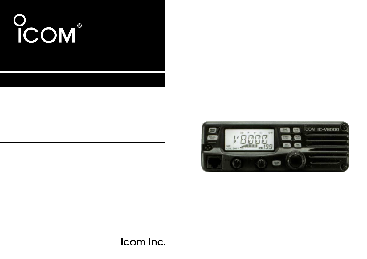
INSTRUCTION MANUAL
iV8000
VHF FM TRANSCEIVER
This device complies with Part 15 of the FCC rules. Operation is subject to the following two conditions: (1) This device may not cause
harmful interference, and (2) this device must accept any interference
received, including interference that may cause undesired operation.
i
FOREWORD
Thank you for purchasing this Icom product. The IC-V8000
VHF FM TRANSCEIVER
is designed and built with Icom’s superior technology and craftsmanship. With proper care, this product should provide you with years of trouble-free operation.
We want to take a couple of moments of your time to thank
you for making your IC-V8000 your radio of choice, and hope
you agree with Icom’s philosophy of “technology first.” Many
hours of research and development went into the design of
your IC-V8000.
DD
FEATURES
❍ 75 W* of high transmit output power
(except Taiwan version)
❍ Front mounted speaker for clear audio
readability
❍ Tone squelch, DTCS squelch standard
❍ Dual color (amber & green) LCD backlight
❍ Remote control microphone available
(optional for some versions)
❍ Optional DTMF decoder
IMPORTANT
READ ALL INSTRUCTIONS carefully and completely
before using the transceiver.
SAVE THIS INSTRUCTION MANUAL— This in-
struction manual contains important operating instructions for
the IC-V8000.
EXPLICIT DEFINITIONS
WORD DEFINITION
R WARNING!
CAUTION
NOTE
Personal injury, fire hazard or electric shock
may occur.
Equipment damage may occur.
Recommended for optimum use. No risk of
personal injury, fire or electric shock.
Icom, Icom Inc. and the logo are registered trademarks of Icom
Incorporated (Japan) in the United States, the United Kingdom, Germany, France, Spain, Russia and/or other countries.

RWARNING RF EXPOSURE! This device emits
Radio Frequency (RF) energy. Extreme caution should be observed when operating this device. If you have any questions regarding RF exposure and safety standards please refer to the
Federal Communications Commission Office of Engineering and
Technology’s report on Evaluating Compliance with FCC Guidelines for Human Radio frequency Electromagnetic Fields (OET
Bulletin 65)
RWARNING! NEVER connect the transceiver to an AC
outlet. This may pose a fire hazard or result in an electric shock.
RWARNING! NEVER operate the transceiver while dri-
ving a vehicle. Safe driving requires your full attention—anything
less may result in an accident.
NEVER connect the transceiver to a power source of more
than 16 V DC. This will ruin the transceiver.
NEVER connect the transceiver to a power source using re-
verse polarity. This will ruin the transceiver.
NEVER cut the DC power cable between the DC plug and
fuse holder. If an incorrect connection is made after cutting, the
transceiver may be damaged.
NEVER expose the transceiver to rain, snow or any liquids.
The transceiver may be damaged.
NEVER operate or touch the transceiver with wet hands. This
may result in an electric shock or ruin the transceiver.
NEVER place the transceiver where normal operation of the
vehicle may be hindered or where it could cause bodily injury.
NEVER let objects impede the operation of the cooling fan on
the rear panel.
DO NOT
push the PTT when not actually desiring to transmit.
DO NOT allow children to play with any radio equipment con-
taining a transmitter.
During mobile operation,
DO NOT operate the transceiver
without running the vehicle’s engine. When the transceiver’s
power is ON and your vehicle’s engine is OFF, the vehicle’s battery will soon become exhausted.
BE CAREFUL! The transceiver will become hot when op-
erating it continuously for long periods.
AVOID using or placing the transceiver in direct sunlight or in
areas with temperatures below –10°C (+14˚F) or above +60°C
(+140˚F).
AVOID the use of chemical agents such as benzine or alcohol
when cleaning, as they can damage the transceiver’s surfaces.
USE Icom microphones only (supplied or optional). Other man-
ufacturer’s microphones have different pin assignments and may
damage the transceiver if attached.
ii
CAUTIONS
iii
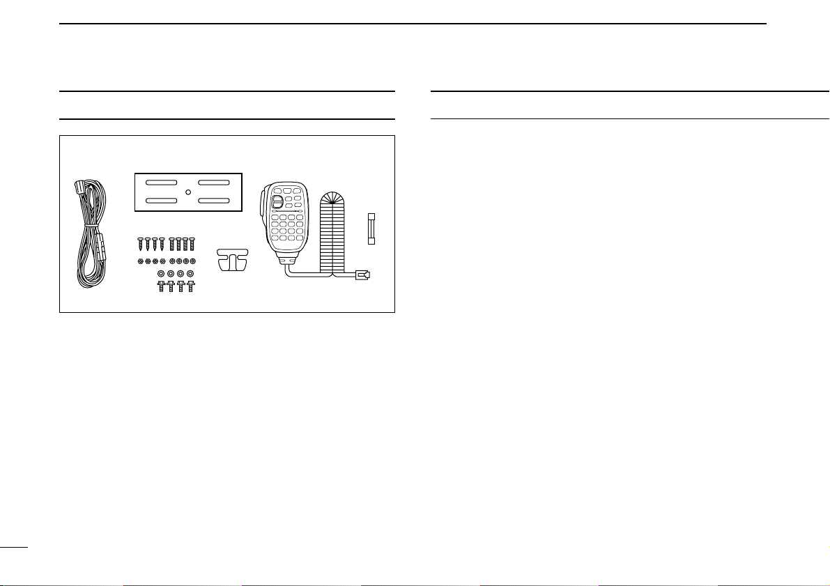
TABLE OF CONTENTSSUPPLIED ACCESSORIES
q DC power cable (3 m) . . . . . . . . . . . . . . . . . . . . . . . . . . . 1
w Mobile mounting bracket . . . . . . . . . . . . . . . . . . . . . . . . 1
e Microphone (HM-133V)* . . . . . . . . . . . . . . . . . . . . . . . . . 1
r Fuse (20 A) . . . . . . . . . . . . . . . . . . . . . . . . . . . . . . . . . . . 1
t Mounting screws, nuts and washers . . . . . . . . . . . . 1 set
y Microphone hanger
†
. . . . . . . . . . . . . . . . . . . . . . . . . . . . 1
*HM-118N
HAND MICROPHONE
or HM-118TN/TAN
DTMF MICROPHONE
supplied versions are also available.
†
Depending on version.
FOREWORD ………………………………………………………………………………. i
IMPORTANT ……………………………………………………………………………….. i
EXPLICIT DEFINITIONS ………………………………………………………………. i
CAUTIONS ………………………………………………………………………………… ii
SUPPLIED ACCESSORIES ………………………………………………………… iii
TABLE OF CONTENTS ………………………………………………………………. iii
QUICK REFERENCE GUIDE …………………………………………………… I–VI
■ Installation …………………………………………………………………………… I
■ Your first contact ………………………………………………………………… IV
■ Repeater operation ……………………………………………………………… V
■ Programming memory ………………………………………………………… VI
1 PANEL DESCRIPTION ……………………………………………………….. 1–8
■ Front panel …………………………………………………………………………. 1
■ Function display ………………………………………………………………….. 3
■ Rear panel …………………………………………………………………………. 5
■ Microphone (HM-133V) ………………………………………………………… 6
■ Microphone keypad ……………………………………………………………… 7
2 SETTING A FREQUENCY …………………………………………………. 9–12
■ Preparation ………………………………………………………………………… 9
■ Using the tuning dial ……………………………………………………………. 9
■ Using the keypad ………………………………………………………………. 10
■ Using the [Y]/[Z] keys ……………………………………………………….. 10
■ Tuning step selection …………………………………………………………. 11
■ Lock functions …………………………………………………………………… 12
3 BASIC OPERATION ……………………………………………………….. 13–16
■ Receiving …………………………………………………………………………. 13
■ Monitor function ………………………………………………………………… 13
■ Audio mute function …………………………………………………………… 14
■ Squelch attenuator …………………………………………………………….. 14
■ Transmitting ……………………………………………………………………… 15
■ Selecting output power ………………………………………………………. 15
■ One-touch PTT function ……………………………………………………… 16

iv
1
2
3
4
5
6
7
8
9
10
11
12
13
14
15
4 REPEATER OPERATION ………………………………………………… 17–23
■ Accessing a repeater …………………………………………………………. 17
■ Subaudible tones ………………………………………………………………. 19
■ Offset frequency ……………………………………………………………….. 21
■ Repeater lockout ……………………………………………………………….. 21
■ Reverse duplex mode ………………………………………………………… 22
■ Auto repeater ……………………………………………………………………. 23
5 MEMORY OPERATION …………………………………………………… 24–34
■ General description ……………………………………………………………. 24
■ Memory channel selection ………………………………………………….. 24
■ Programming a memory channel …………………………………………. 25
■ Transferring memory contents …………………………………………….. 27
■ Memory clearing ……………………………………………………………….. 29
■ Channel names programming ……………………………………………… 30
■ Memory bank selection ………………………………………………………. 32
■ Memory bank setting ………………………………………………………….. 33
■ Transferring bank contents …………………………………………………. 34
6 CALL CHANNEL OPERATION ………………………………………… 35–36
■ Call channel selection ………………………………………………………… 35
■ Call channel transferring …………………………………………………….. 35
■ Programming a call channel ……………………………………………….. 36
7 SCAN OPERATION ………………………………………………………… 37–42
■ Scan types ……………………………………………………………………….. 37
■ Scan start/stop ………………………………………………………………….. 38
■ Scan edges programming …………………………………………………… 39
■ Skip channel setting …………………………………………………………… 41
■ Scan resume condition ………………………………………………………. 42
8 PRIORITY WATCH ………………………………………………………….. 43–44
■ Priority watch types ……………………………………………………………. 43
■ Priority watch operation ……………………………………………………… 44
9 DTMF MEMORY ENCODER …………………………………………….. 45–47
■ Programming a DTMF code ………………………………………………… 45
■ Transmitting a DTMF code …………………………………………………. 46
■ DTMF speed …………………………………………………………………….. 47
10 POCKET BEEP AND TONE SQUELCH …………………………….. 48–51
■ Pocket beep operation ……………………………………………………….. 48
■ Tone/DTCS squelch operation …………………………………………….. 50
■ Tone scan …………………………………………………………………………. 51
11 PAGER/CODE SQUELCH ……………………………………………….. 52–57
■ Pager function …………………………………………………………………… 52
■ Code programming ……………………………………………………………. 52
■ Pager operation ………………………………………………………………… 55
■ Code squelch ……………………………………………………………………. 57
12 OTHER FUNCTIONS ………………………………………………………. 58–70
■ Set mode ………………………………………………………………………….. 58
■ Initial set mode ………………………………………………………………….. 62
■ Weather channel operation …………………………………………………. 65
■ Microphone keys ……………………………………………………………….. 67
■ Partial reset ………………………………………………………………………. 68
■ All reset ……………………………………………………………………………. 68
■ Data cloning ……………………………………………………………………… 69
13 MAINTENANCE ……………………………………………………………… 71–73
■ Troubleshooting ………………………………………………………………… 71
■ Fuse replacement ……………………………………………………………… 72
■ Optional unit installation ……………………………………………………… 73
14 SPECIFICATIONS AND OPTIONS …………………………………………. 74
15 MODE ARRANGEMENT ………………………………………………….. 75–76
I
QUICK REFERENCE GUIDE
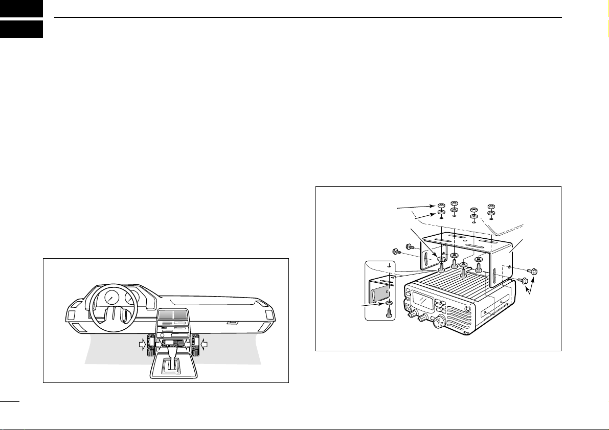
■ Installation
D Location
Select a location which can support the weight of the transceiver and does not interfere with driving in any way. We recommend the locations shown in the diagram below.
NEVER place the transceiver where normal operation of the
vehicle may be hindered or where it could cause bodily injury.
NEVER place the transceiver where air bag deployment may
be obstructed.
DO NOT place the transceiver where hot or cold air blows directly onto it.
AVOID placing the transceiver in direct sunlight.
D Using the mounting bracket
➀ Drill 4 holes where the mounting bracket is to be installed.
• Approx. 5.5–6 mm (1⁄4″) when using nuts; approx. 2–3 mm (1⁄8″)
when using self-tapping screws.
➁ Insert the supplied screws, nuts and washers through the
mounting bracket and tighten.
➂ Adjust the angle for the clearest view of the function dis-
play.
Nut
Spring washer
Flat washer
Spring
washer
When using
self-tapping
screws
Mounting
nut
Mounting
bracket
• Example— Installation location
II
QUICK REFERENCE GUIDE
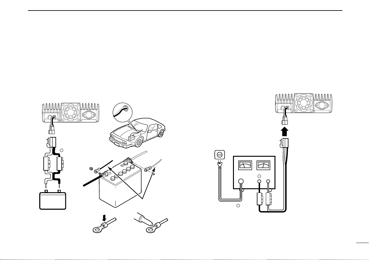
D Battery connection
☞ NEVER connect the transceiver directly to a 24 V battery.
☞ DO NOT use the cigarette lighter socket for power con-
nections. (See p. 5 for details)
Attach a rubber grommet when passing the DC power cable
through a metal plate to prevent short circuiting.
• CONNECTING TO A DC POWER SOURCE
• See p. 72 for fuse replacement.
D DC power supply connection
Use a 13.8 V DC power supply with at least 15 A capacity.
Make sure the ground terminal of the DC power supply is
grounded.
• CONNECTING TO A DC POWER SUPPLY
• See p. 72 for fuse replacement.
DC power
supply 13.8 V
to an
AC
outlet
Fuses
20 A
black
red⊕
−
⊕
−
IC-V8000
Fuses
20 A
Crimp Solder
black
red⊕
Grommet
IC-V8000
−
12 V
12 V
battery
Supplied
DC power cable
NOTE:
Use terminals for the
cable connections.
+ red
_ black
III
QUICK REFERENCE GUIDE
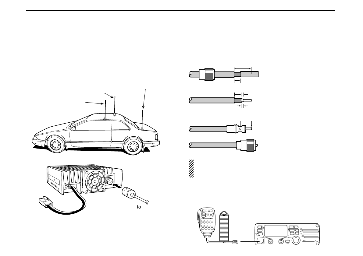
D Antenna installation
• Antenna location
To obtain maximum performance from the transceiver, select
a high-quality antenna and mount it in a good location. A nonradial antenna should be used when using a magnetic mount.
• Antenna connector
The antenna uses a PL-259 connector.
• PL-259 CONNECTOR
q Slide the coupling ring
down. Strip the cable
jacket and soft solder.
w Strip the cable as shown
at left. Soft solder the center conductor.
e Slide the connector body
on and solder it.
r Screw the coupling ring
onto the connector body.
(10 mm ≈3⁄8 in)
NOTE: There are many publications covering proper antennas and their installation. Check with your local dealer
for more information and recommendations.
D Connecting a microphone
Connect a microphone to the eight-pin modular socket on the
front panel of the transceiver.
*HM-133V; A different microphone may be
supplied with some versions of the IC-V8000.
30 mm
10 mm (soft solder)
10 mm
1–2 mm
solder solder
Soft
solder
Coupling ring
Roof-mount antenna
(Drill a hole or use a magnetic mount.)
Gutter-mount antenna
Trunk-mount
antenna
IV
QUICK REFERENCE GUIDE
■ Your first contact
Now that you have your IC-V8000 installed in your car or
shack, you are probably excited to get on the air. We would
like to take you through a few basic operation steps to make
your first “On The Air” an enjoyable experience.
1. Turning ON the transceiver
Before powering up your IC-V8000, you may want to make
sure the audio volume and squelch level controls are set in
9–10 o’clock positions.
Although you have purchased a brand new transceiver, some
settings may be changed from the factory defaults because
of the QC process. Resetting the CPU is necessary to start
from factory default.
➥ While pushing [SET(LOCK)] and [MW(S.MW)], push
[PWR] for 1 sec. to reset the CPU.
2. Tune the desired frequency
The tuning dial will allow you to dial in the frequency you want
to operate. Pages 9 and 11 will instruct you on how to set the
tuning speed.
Using the HM-133V
You can directly enter the frequency with the HM-133V keypad.
We hope these pointers have been helpful. Now you
are ready to call CQ.
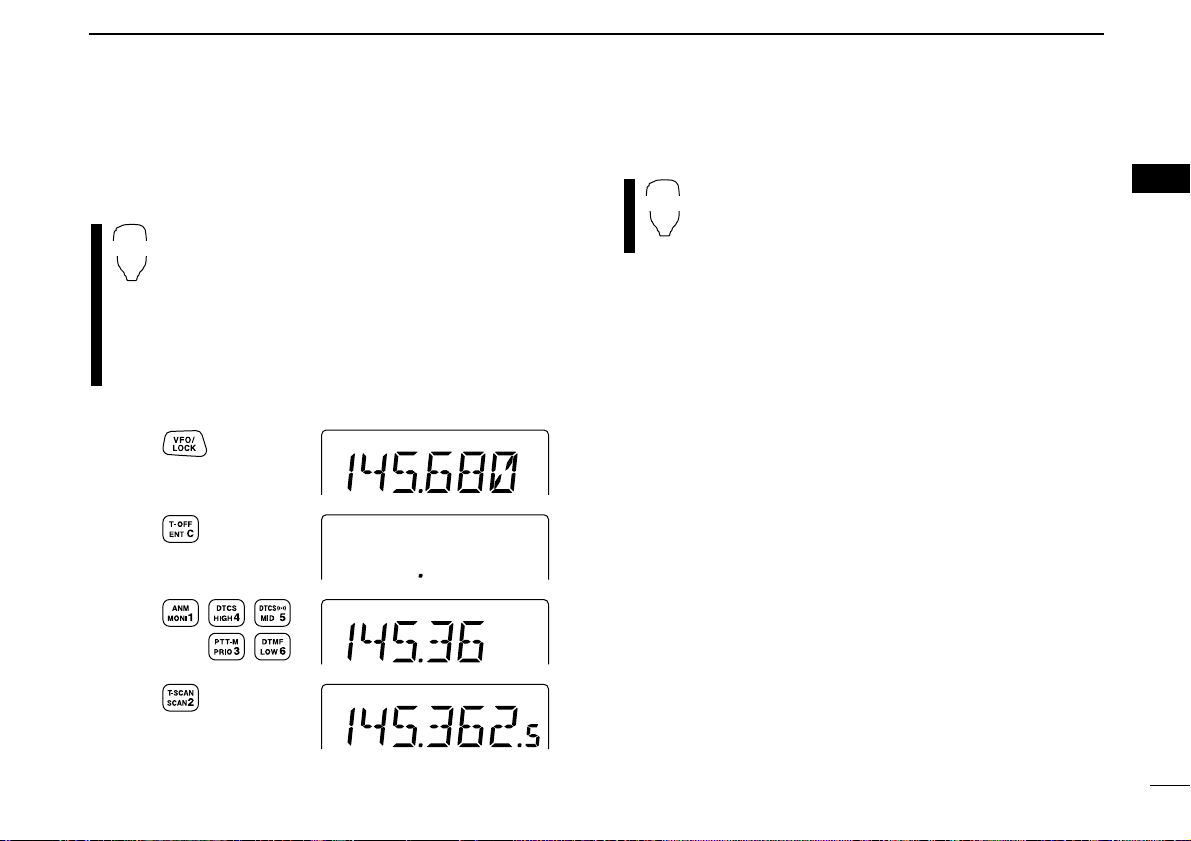
[EXAMPLE]: Setting frequency to 145.3625 MHz.
Push
Push
Push
Push
[PWR] [SET(LOCK)] [MW(S.MW)]
Set both [VOL] and [SQL] controls to
9–10 o’clock positions.
V
QUICK REFERENCE GUIDE
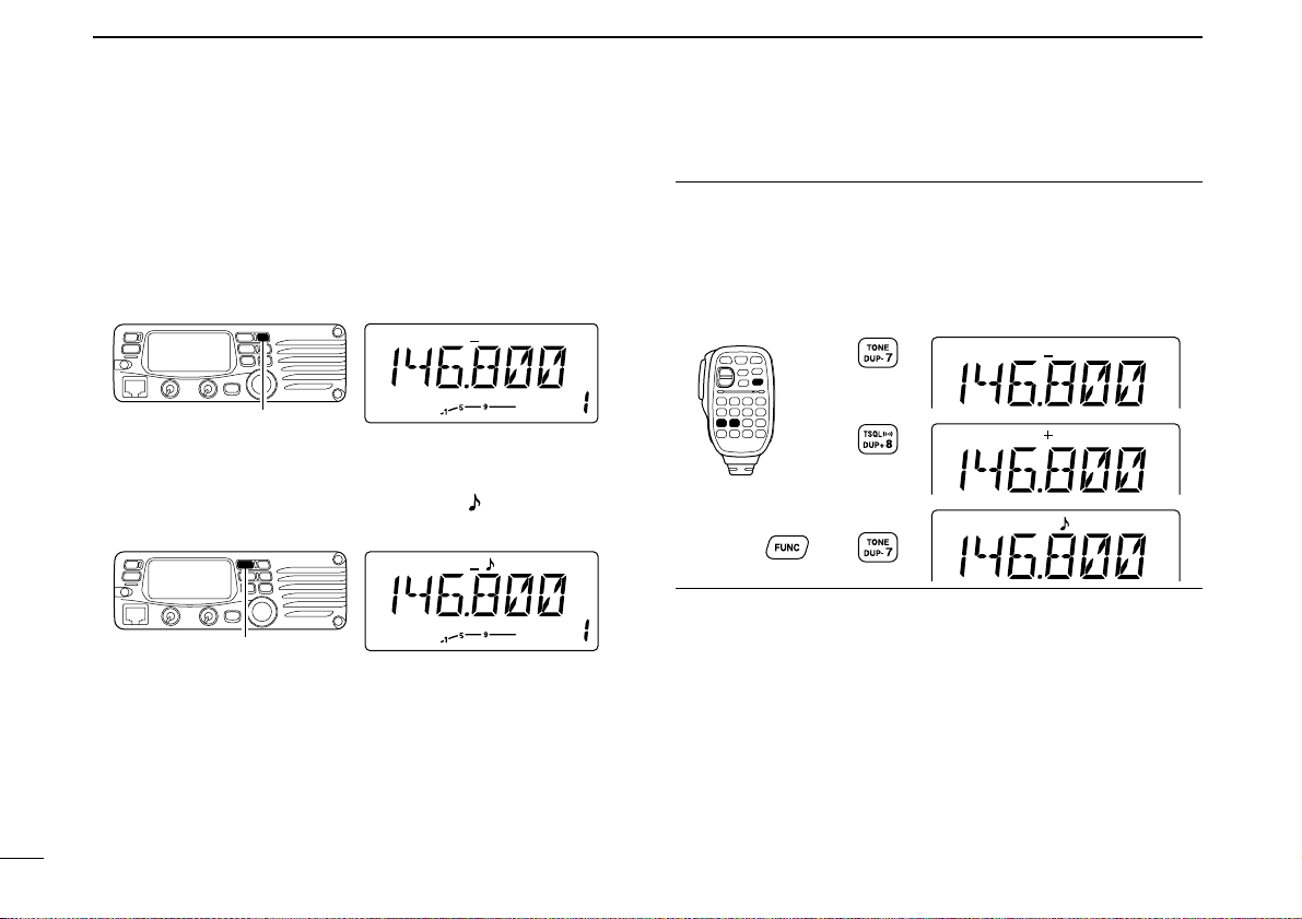
■ Repeater operation
1. Setting duplex
Push [LOW(DUP)] for 1 sec. once or twice to select minus duplex or plus duplex.
• The USA and CSA versions have an auto repeater function, therefore, setting duplex is not required.
2. Repeater tone
Push [TONE(T-SCAN)] several times until “” appears, if the
repeater requires a subaudible to be accessed.
Using the HM-133V
Plus or minus duplex selection and the repeater tone setting
can be made easily via HM-133V.
Push [
DUP
– 7(TONE)] for minus duplex; [
DUP
+ 8(TSQLS)]
for plus duplex selection, push [FUNC] then [
DUP
– 7(TONE)]
to turn the repeater tone ON.
VI
QUICK REFERENCE GUIDE
■ Programming memory
channels
The IC-V8000 has a total of 200 memory channels (including
6 scan edges and 1 call channel) for storing often used operating frequency, repeater settings, etc.
1. Setting a frequency
In VFO mode, set the desired operating frequency with repeater, tone and tuning steps, etc.
2. Selecting a memory channel
Momentarily push [MW(S.MW)], then rotate the tuning dial to
select the desired memory channel.
•“M” indicator and memory channel number blink.
3. Writing a memory channel
Push and hold [MW(S.MW)] for 1 sec. to program.
• 3 beeps sound
• Memory channel number automatically increases when continuing
to push [MW(S.MW)] after programming.
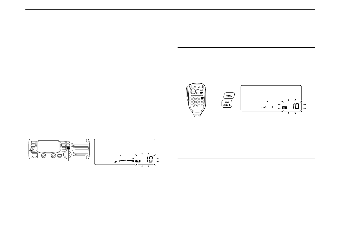
Using the HM-133V
q In VFO mode, set the desired operating frequency, includ-
ing offset direction, tone settings, etc.
w Push [FUNC] then [
CLR
A(MW)].
•“M” indicator and memory channel number blink.
e Push [Y]/[Z] to select the desired memory channel.
r Push [FUNC] then push [
CLR
A(MW)] for 1 sec. to pro-
gram.
• 3 beeps sound
• Memory channel number automatically increases when continu-
ing to push [
CLR
A(MW)] after programming.
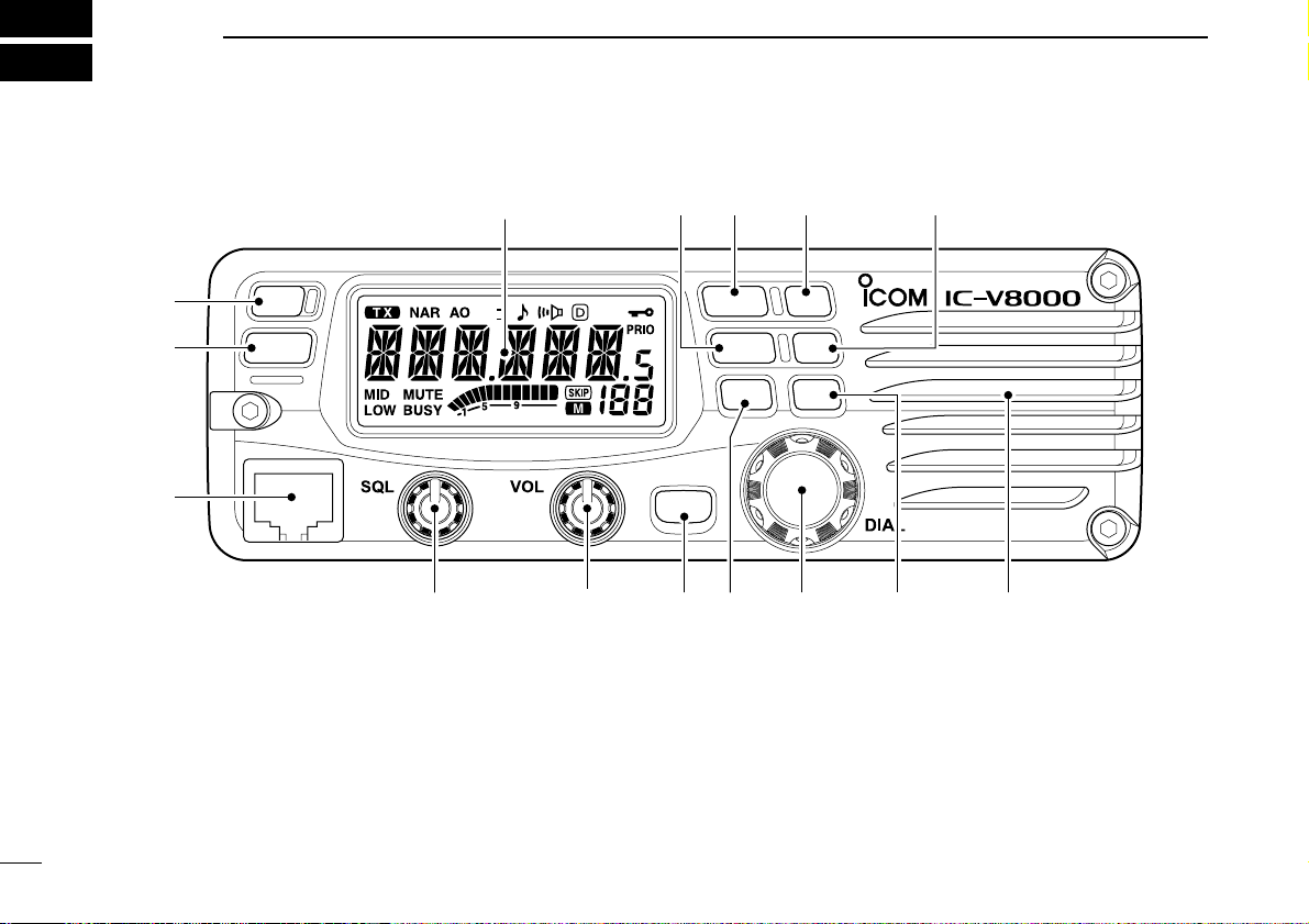
■ Front panel
q POWER SWITCH [PWR]
Turns power ON and OFF when pushed for 1 sec.
w MEMORY/CALL•PRIORITY SWITCH [M/CALL(PRIO)]
➥ Push to select and toggle memory, call and weather
channel* modes. (pgs. 24, 35, 65)
*Weather channels available for USA versions only.
➥ Starts priority watch when pushed for 1 sec. (p. 44)
e MICROPHONE CONNECTOR
Connects the supplied microphone.
r SQUELCH CONTROL [SQL]
Varies the squelch level. (p. 13)
• The RF attenuator activates and increases the attenuation when
rotated clockwise to the center position and further.
t VOLUME CONTROL [VOL]
Adjusts the audio level. (p. 13)
OPT
BANK
V/MHz
SCAN
LOW
DUP
MONI
ANM
SET
LOCK
PWR
S.MW
MW
T-SCAN
TONE
PRIO
M/CALL
t
Function display (p. 3)
q
w
e
ryuioSpeaker
!0!1!2!3

2
1
PANEL DESCRIPTION
1
y BANK•OPTION SWITCH [BANK(OPT)]
➥ Push to select memory bank condition during memory
mode. (p. 32)
➥ Push for 1 sec. to select and toggle the pager and code
squelch function when the optional UT-108 is installed.
(p. 52)
u SET•LOCK SWITCH [SET(LOCK)]
➥ Enters set mode when pushed. (p. 58)
➥ Switches the lock function ON and OFF when pushed
for 1 sec. (p. 12)
i TUNING DIAL [DIAL]
Selects the operating frequency (p. 9), memory channel
(p. 24), the setting of the set mode item and the scanning
direction (p. 38).
o MEMORY WRITE SWITCH [MW(S.MW)] (p. 25)
➥ Selects a memory channel for programming.
➥ Programs the selected memory channel when pushed
for 1 sec.
• Continue to hold the switch to increment the memory channel automatically.
!0 MONITOR•CHANNEL NAME SWITCH [MONI(ANM)]
➥ Push to switch the monitor function ON and OFF. (p. 13)
➥ In memory and call channel mode, switches the channel
names or number ON and OFF. (p. 30)
!1 OUTPUT POWER SWITCH [LOW(DUP)]
➥ Each push changes the output power selection. (p. 15)
➥ Select DUP–, DUP+ and simplex operation when
pushed for 1 sec. (p. 17)
!2 TONE/TONE SCAN SWITCH [TONE(T-SCAN)]
➥ Each push selects a tone function. (pgs. 17, 48)
• Tone encoder, pocket beep, tone squelch or tone function
OFF can be selected.
➥ Push for 1 sec. to start/stop the tone scan function.
(p. 51)
!3 VFO/MHz TUNING•SCAN SWITCH [V/MHz(SCAN)]
➥ Selects and toggles VFO mode and 1 MHz (or 10 MHz
for some versions) tuning when pushed. (p. 9)
➥ Starts scan when pushed for 1 sec. (p. 38)
• Cancels a scan when pushed during scan.
D Microphone connector (front panel view)
q +8 V DC output (Max. 10 mA)
w Channel up/down
e 8 V control IN
r PTT
t GND (microphone ground)
y MIC (microphone input)
u GND
i Data IN
3
1 PANEL DESCRIPTION
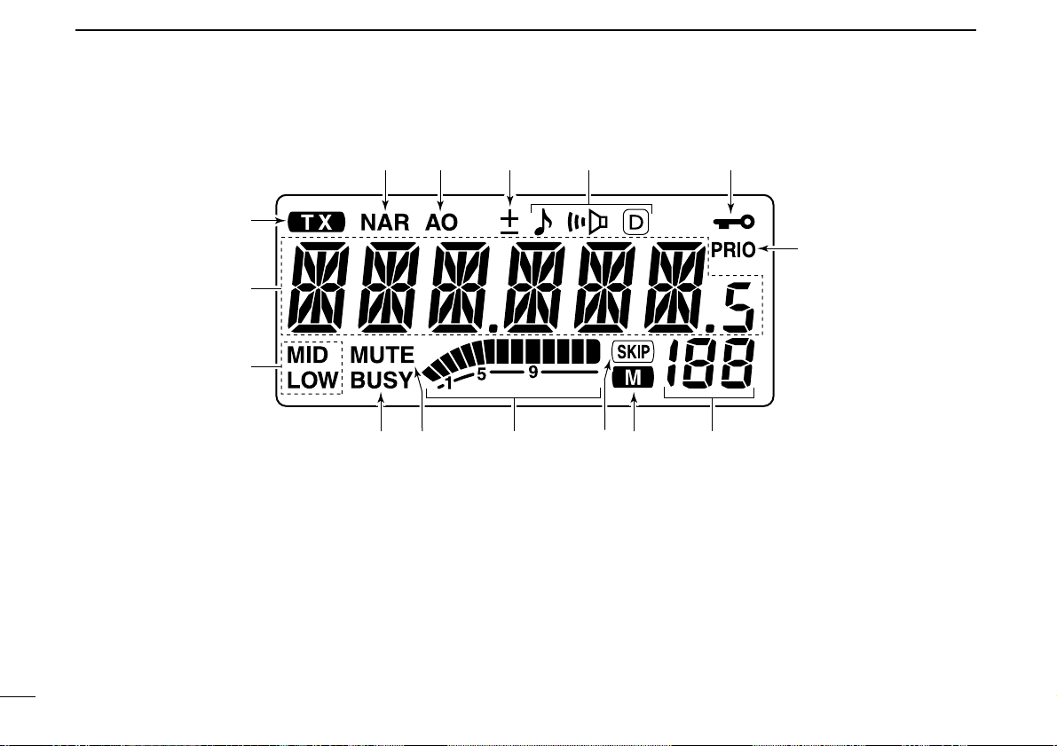
■ Function display
qTRANSMIT INDICATOR
➥ Appears while transmitting. (p. 15)
➥ Flashes while transmitting with the one-touch PTT func-
tion. (p. 16)
wFREQUENCY READOUT
Shows the operating frequency, channel names, set mode
contents, etc.
• Frequency decimal point flashes while scanning. (p. 38)
•“d” appears in place of the 1st digit while the DTMF memory
function is in use. (p. 45)
eOUTPUT POWER INDICATORS
“LOW” appears when low output power; “LOW” and “MID”
appear when low mid output power; “MID” appears when
middle output power is selected
rBUSY INDICATOR (p. 13)
➥ Appears when a signal is being received or the squelch
is open.
➥ Flashes while the monitor function is activated.
tAUDIO MUTE INDICATOR (p. 14)
Appears when the audio mute function is activated via microphone control.
t
q
w
e
ryuio
!3!4!5
!0
!1!2

4
1
PANEL DESCRIPTION
1
yS/RF INDICATORS
➥ Shows the relative signal strength while receiving sig-
nals. (p. 13)
➥ Shows the output power level while transmitting. (p. 15)
uSKIP INDICATOR (p. 41)
Appears when the displayed memory channel is specified
as a skip channel.
iMEMORY INDICATOR (p. 24)
Appears when memory mode is selected.
oMEMORY CHANNEL NUMBER INDICATORS
➥ Shows the selected memory channel number. (p. 24)
➥ “C” appears when the call channel is selected. (p. 35)
!0PRIORITY WATCH INDICATOR (p. 44)
Appears while the priority watch is activated; blinks while
the watch is paused.
!1LOCK INDICATOR (p. 12)
Appears when the lock function is activated.
!2TONE INDICATORS
➥ “” appears while the subaudible tone encoder is in
use. (p. 17)
➥ “” appears while the tone
(CTCSS) squelch function is
in use. (p. 48)
➥ “” appears while the tone
(DTCS) squelch function is
in use. (p. 48)
➥ “” appears with the “” or “” indicator while the
pocket beep function
(CTCSS or DTCS) is in use. (p. 48)
!3DUPLEX INDICATORS (p. 17)
“+” appears when plus duplex, “–” appears when minus
duplex operation is selected.
!4AUTO POWER-OFF INDICATOR (p. 64)
Appears while the auto power-off function is in use.
!5NARROW MODE INDICATOR (p. 61)
Appears when the narrow mode is selected.
Narrow mode is available with some USA versions only.
5
1 PANEL DESCRIPTION
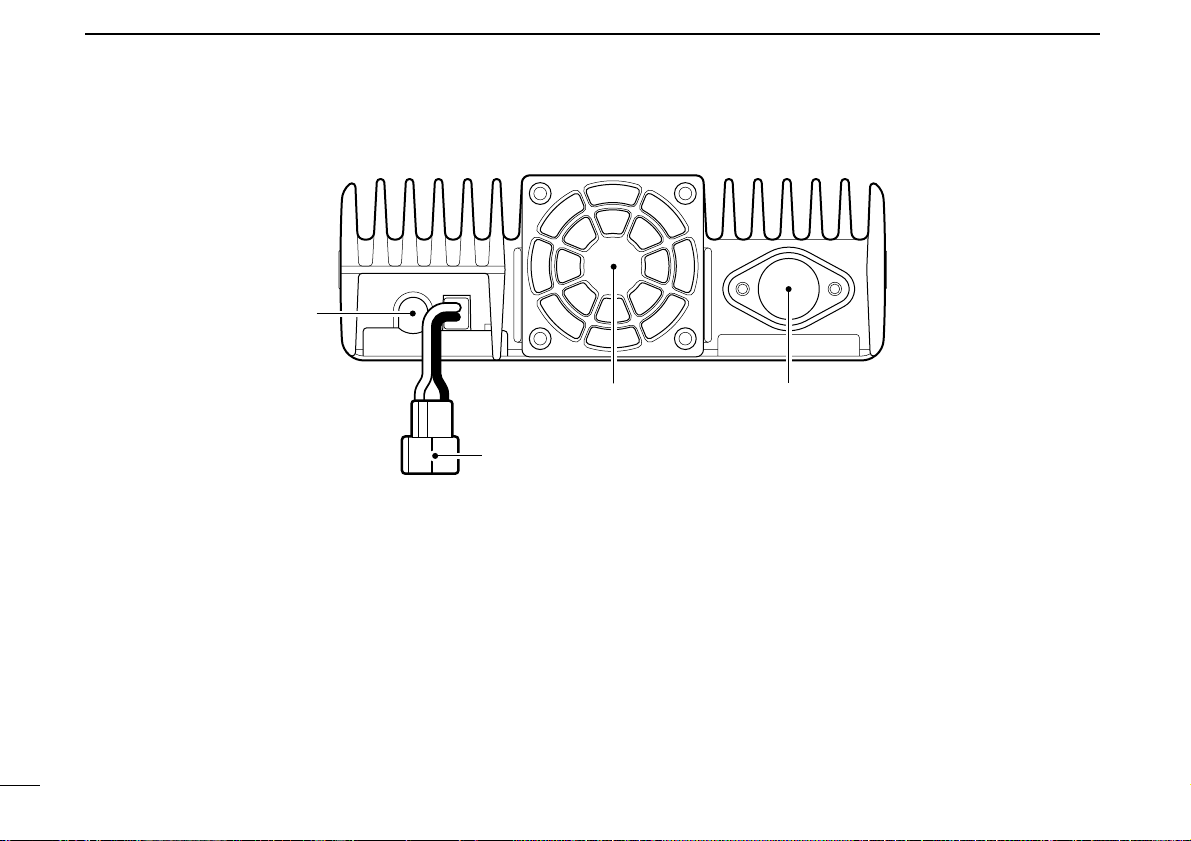
■ Rear panel
q SPEAKER JACK [SP]
Accepts an 8 Ω speaker.
• Audio output power is more than 2.0 W.
w POWER RECEPTACLE [DC13.8V]
Accepts 13.8 V DC ±15% with the supplied DC power
cable.
☞ NOTE: DO NOT use a cigarette lighter socket as a
power source when operating in a vehicle. The plug
may cause voltage drops and ignition noise may be superimposed onto transmit or receive audio.
e COOLING FAN
Rotates while transmitting.
Also rotates while receiving depending on the setting in set
mode and transceiver’s temperature. (p. 61)
r ANTENNA CONNECTOR [ANT]
Connects a 50 Ω antenna with a PL-259 connector and a
50 Ω coaxial cable.
6
1
PANEL DESCRIPTION
1
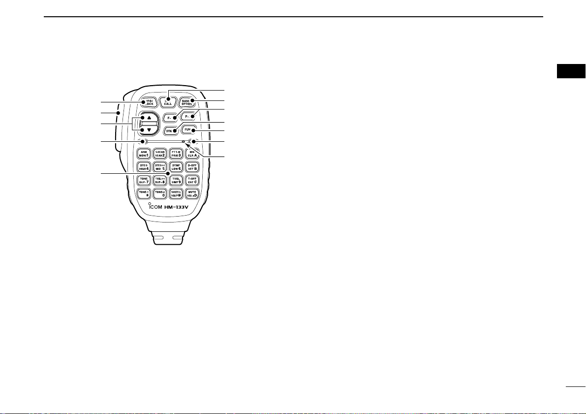
■ Microphone (HM-133V*)
qVFO/LOCK SWITCH [VFO/LOCK]
➥ Push to select VFO mode. (p. 9)
➥ Push for 1 sec. to switch the lock function ON and OFF.
(p. 12)
wPTT SWITCH
➥ Push and hold to transmit; release to receive.
➥ Switches between transmitting and receiving while the
one-touch PTT function is in use. (p. 16)
eUP/DOWN SWITCHES [Y]/[Z]
➥ Push either switch to change operating frequency,
memory channel, set mode setting, etc. (pgs. 10, 24)
➥ Push either switch for 1 sec. to start scanning. (p. 38)
rACTIVITY INDICATOR
➥ Lights red while any key, except [FUNC] and [DTMF-S],
is pushed, or while transmitting.
➥ Lights green while the one-touch PTT function is in use.
tKEYPAD (pgs. 7, 
yFUNCTION INDICATOR
➥ Lights orange while [FUNC] is activated—indicates the
secondary function of switches can be accessed.
➥ Lights green when [DTMF-S] is activated—DTMF sig-
nals can be transmitted with the keypad.
uFUNCTION SWITCH [FUNC] (pgs. 7,
iDTMF MEMORY SELECT SWITCH [DTMF-S] (p. 46)
oFUNCTION SWITCHES [F-1]/[F-2] (p. 67)
Program and re-call your desired transceiver conditions.
!0BANK/OPTION SWITCH [BANK/OPTION]
➥ Push to selects memory bank condition during memory
mode. (p. 32)
➥ Push for 1 sec. to select and toggle pager and code
squelch function when the optional UT-108 is installed.
(p. 52)
!1MEMORY/CALL SWITCH [MR/CALL]
➥ Push to select memory mode. (p. 24)
➥ Push for 1 sec. to select call channel. (p. 35)
q
e
r
t
Mic element
y
u
i
o
!0
!1
w
*
A different microphone
may be supplied depending on version.
7
1 PANEL DESCRIPTION
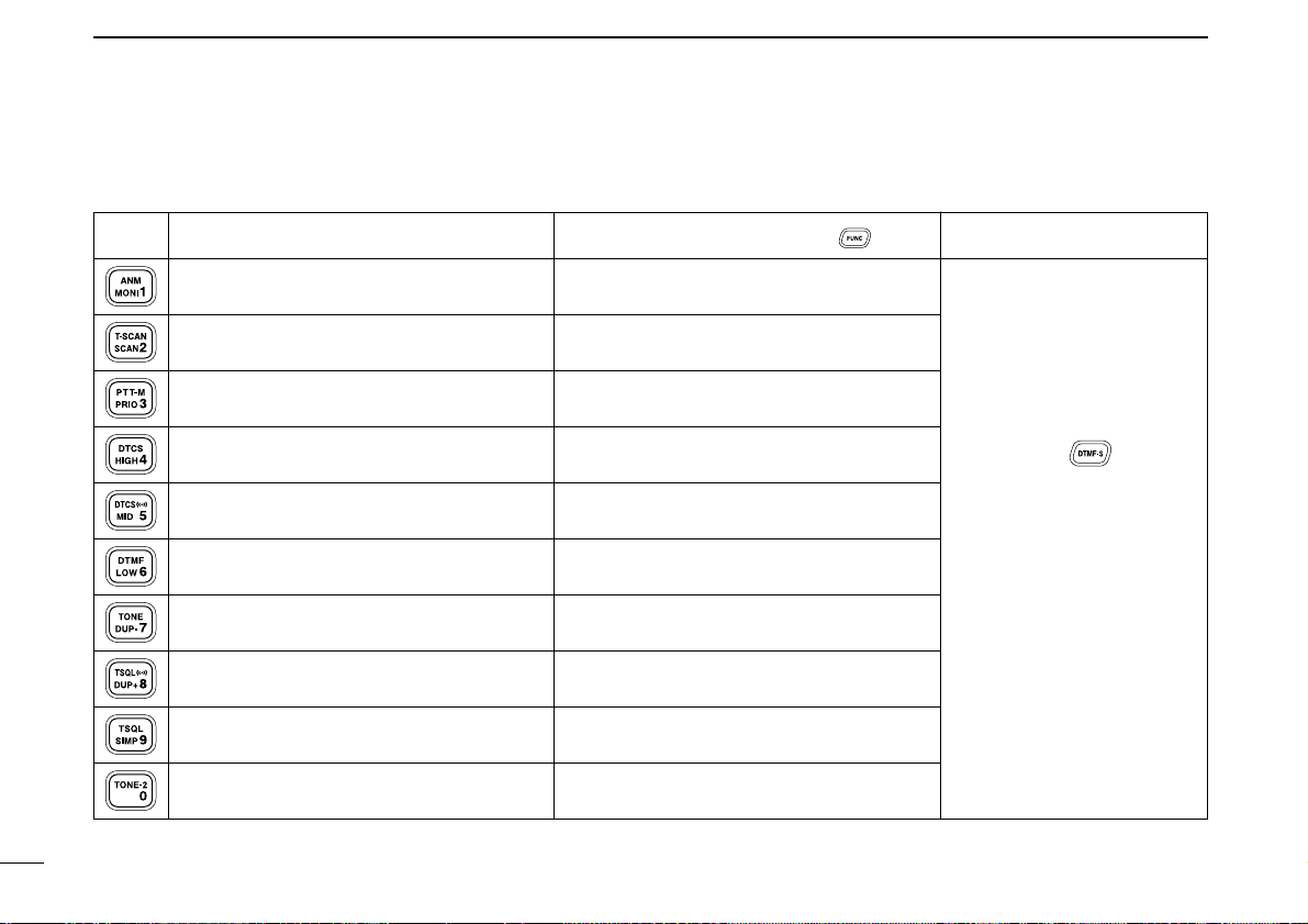
■ Microphone keypad
KEY FUNCTION SECONDARY FUNCTION ( +key) OTHER FUNCTIONS
Switches between opening and closing the
squelch. (p. 13)
Starts and stops scanning. (p. 38)
Starts and stops priority watch. (p. 44)
Selects high output power. (p. 15)
Selects mid. output power. (p. 15)
Selects low output power (p. 15)
Selects minus duplex operation. (p. 18)
Selects plus duplex operation. (p. 18)
Selects simplex operation. (p. 18)
No primary function.
In memory mode switches the channel names
or number indication ON and OFF. (p. 31)
Starts and stops tone scanning. (p. 51)
Turns the one-touch PTT function ON and
OFF. (p. 16)
Turns the DTCS squelch ON. (p. 50)
Turns the DTCS pocket beep function ON.
(p. 49)
Turns the DTMF memory encoder function
ON. (p. 45)
Turns the subaudible tone encoder ON.
(p. 18)
Turns the CTCSS pocket beep function
ON. (p. 49)
Turns the tone squelch function ON.
(p. 50)
Sends a 1750 Hz tone signal while pushing
and holding. (p. 20)
After pushing :
Transmits the appropriate
DTMF code. (pgs. 20, 46)
When the DTMF memory encoder is activated, push [0] to
[9] to transmit the appropriate
DTMF memory contents .
(p. 46)
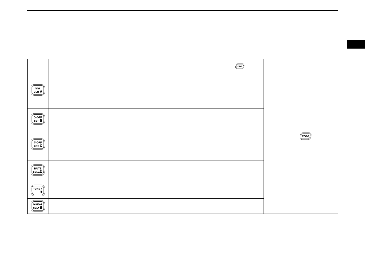
8
1
PANEL DESCRIPTION
1
➥ Cancels frequency entry. (p. 10)
➥ Cancels the scan or priority watch.
(pgs. 38, 44)
➥ Exit set mode. (p. 58)
➥ Enters set mode (p. 58)
➥ Advances the set mode selection order
after entering set mode. (p. 58)
➥ Sets the keypad for numeral input.
(p. 10)
➥ Reverses the set mode selection order
after entering set mode. (p. 58)
Adjusts the squelch level increments.
(p. 13)
No primary function.
Adjusts the squelch level decrement.
(p. 13)
➥ Selects a memory channel for program-
ming. (p. 26)
➥ Advances the memory channel number
when continuously pushed after programming is completed. (p. 26)
DTMF memory OFF. (p. 46)
Turns the subaudible tone encoder, pocket
beep or CTCSS/DTCS tone squelch OFF.
(pgs. 18, 49, 50)
Mutes the audio. (p. 14)
• Mute function is released when any operation is performed.
Sends a 1750 Hz tone signal for 0.5 sec.
(p. 20)
Locks the digit keys on the keypad (including the A to D, # and M keys. (p. 12)
After pushing :
Transmits the appropriate
DTMF code. (pgs. 20, 46)
KEY FUNCTION SECONDARY FUNCTION ( +key) OTHER FUNCTIONS
9
SETTING A FREQUENCY
2
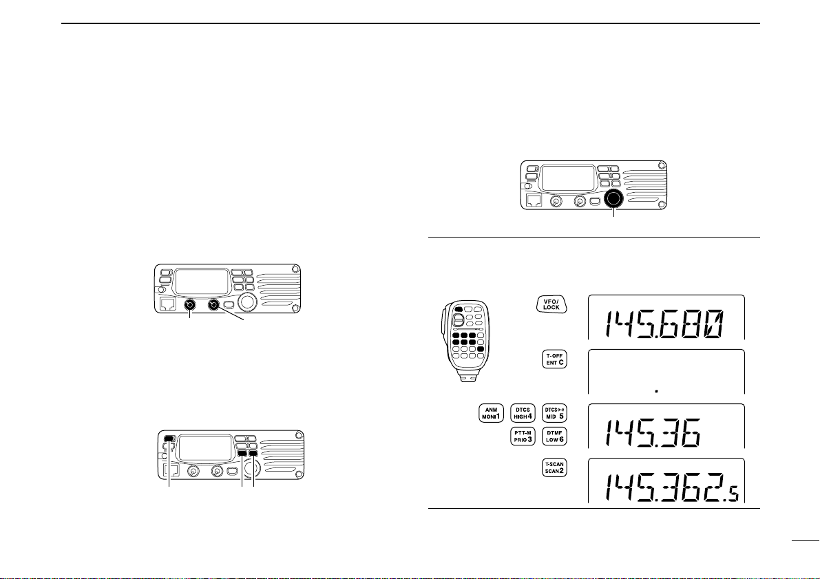
■ Preparation
D Turning power ON/OFF
➥ Push [PWR] for 1 sec. to
turn power ON and OFF.
D VFO mode selection
The transceiver has 2 basic operating modes: VFO mode and
memory mode.
➥ Push [V/MHz(SCAN)] to
select VFO mode.
➥ Push [VFO/LOCK] to select VFO mode.
■ Using the tuning dial
qRotate the tuning dial to set the frequency.
• If VFO mode is not selected,
push [V/MHz(SCAN)] to select
VFO mode.
• The frequency changes according to the selected tuning
steps. (p. 11)
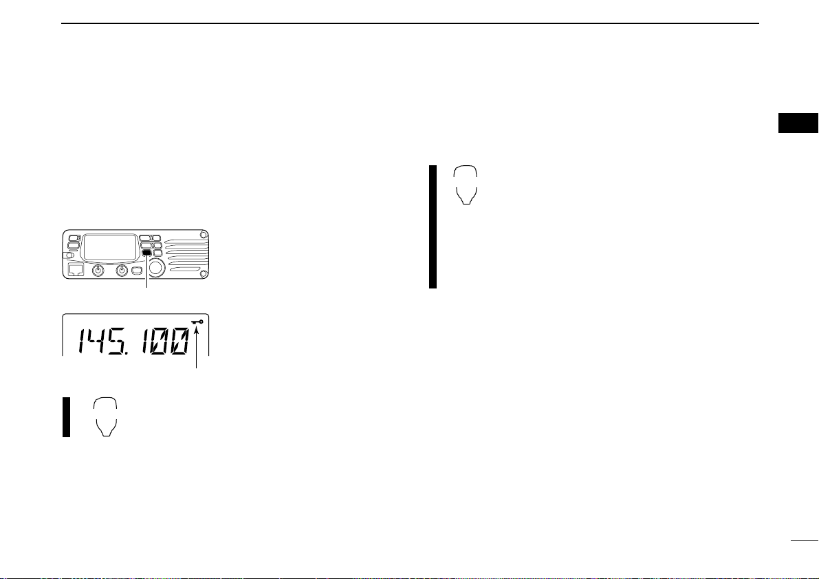
wTo change the frequency in 1 MHz (10 MHz for some ver-
sions) steps, push [V/MHz(SCAN)], then rotate the tuning
dial.
• Pushing [V/MHz(SCAN)] for
1 sec. starts scan function.
If scan starts, push
[V/MHz(SCAN)] again to cancel it.
The display shows that the
1 MHz tuning step is selected.
Note that in this manual, sections beginning with a microphone icon (as above), designate operation via the HM133V microphone.
10
2
SETTING A FREQUENCY
2
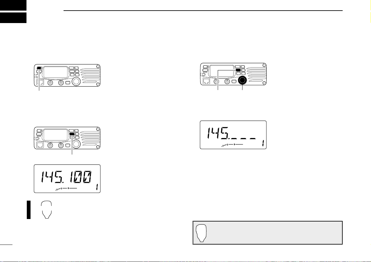
■ Using the keypad
The frequency can be directly set via numeral keys on the microphone.
z Push [VFO/LOCK] to VFO mode, if necessary.
x Push [
ENT
C(T-OFF)] to activate the keypad for
digit input.
c Push 6 keys to input a frequency.
• When a digit is mistakenly input, push [
ENT
C(T-OFF)]
to clear the input, then repeat input from the 1st digit.
• Pushing [
CLR
A(MW)] clears input digits and retrieves
the frequency.
■ Using the [Y]/[Z] keys
➥ Push [Y] or [Z] to select the desired frequency.
• Pushing [Y]/[Z] for 1 sec. activates a scan. If scan
starts, push [Y]/[Z] again or push [
CLR
A(MW)] to can-
cel it.
Push
Push
Push
Push
[EXAMPLE]: Setting frequency to 145.3625 MHz.
11
2 SETTING A FREQUENCY
■ Tuning step selection
Tuning steps are the minimum frequency change increments
when you rotate the tuning dial or push [Y]/[Z] on the microphone. The following tuning steps are available.
• 5 kHz • 10 kHz • 12.5 kHz • 15 kHz
• 20 kHz • 25 kHz • 30 kHz • 50 kHz
☞NOTE: For convenience, select a tuning step that matches
the frequency intervals of repeaters in your area.
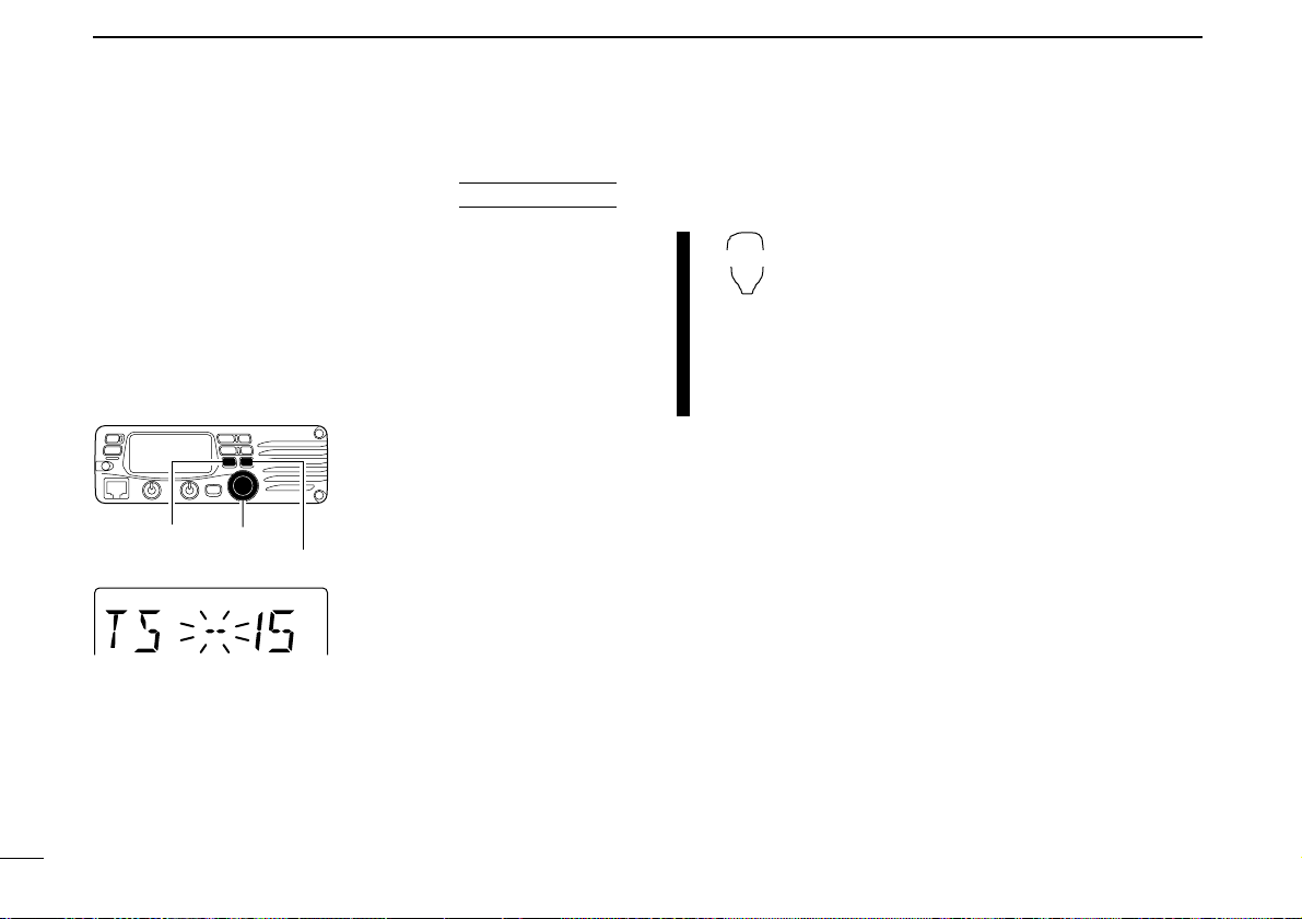
q Push [V/MHz(SCAN)] to se-
lect VFO mode, if necessary.
w Push [SET(LOCK)] to enter
set mode.
e Push [SET(LOCK)] or
[MW(S.MW)] several times
until “TS” appears as shown
at left.
r Rotate the tuning dial to se-
lect the desired tuning step.
t Push [TONE(T-SCAN)] to
exit set mode.
z Push [VFO/LOCK] to select VFO mode, if
necessary.
x Push [
SET
B(D-OFF)] to enter set mode.
c Push [
SET
B(D-OFF)] or [
ENT
C(T-OFF)]
several times until “TS” appears.
v Push [Y] or [Z] to select the desired tuning
step.
b Push [
CLR
A(MW)] to exit set mode.
[SET(LOCK)]
15 kHz tuning step
[MW(S.MW)]
Tuning dial
12
2
SETTING A FREQUENCY
2
■ Lock functions
To prevent accidental channel changes and unnecessary
function access, use the lock function. The transceiver has 2
different lock functions.
D Frequency lock
This function locks the tuning dial and switches electronically
and can be used together with the microphone lock function.
➥ Push [SET(LOCK)] for
1 sec. to turn the lock function ON and OFF.
• [PTT], [MONI(ANM)], [VOL]
and [SQL] can be used while
the channel lock function is in
use. Also, TONE-1, TONE-2,
DTMF tones or DTMF memory contents can be transmitted from the microphone.
➥ Push [VFO/LOCK] for 1 sec. to switch the
lock function ON and OFF.
D Microphone keypad lock
This function locks the microphone keypad.
➥ Push [FUNC] then [
SQL
Z D(16KEY-L)] to
switch the microphone keypad lock function
ON and OFF.
• [PTT], [VFO/LOCK], [MR/CALL], [BANK/OPTION],
[Y], [Z], [F-1], [F-2], [DTMF-S] and [FUNC] on the
microphone can be used.
• All switches on the transceiver can be used.
• The keypad lock function is released when the
power is turned OFF then ON again.
Push [SET(LOCK)] for 1 sec.
Appears
13
BASIC OPERATION
3
■ Receiving
q Push [PWR] for 1 sec. to turn power ON.
w Set the audio level.
➥ Push [MONI(ANM)] to open the squelch.
➥ Rotate the [VOL] control to adjust the audio output level.
➥ Push [MONI(ANM)] again to close the squelch.
e Set the squelch level.
➥ Rotate [SQL] fully counterclockwise in advance.
➥ Rotate [SQL] clockwise until the noise just disappears.
➥ When interference is received, rotate [SQL] clockwise
again for attenuator operation.
r Set the operating frequency. (pgs. 9, 10)
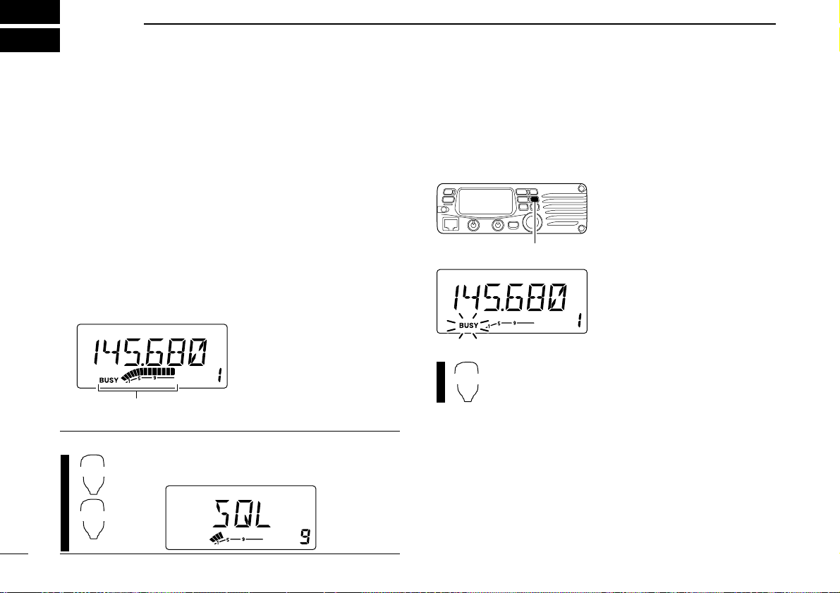
t When receiving a signal on the set frequency, squelch
opens and the transceiver emits audio.
•“BUSY” appears and the S/RF
indicator shows the relative
signal strength for the received signal.
✔
CONVENIENT!
The squelch level can also be adjusted with
[
SQL
Y D(MUTE)] and [
SQL
Z #(16KEY-L)].
■ Monitor function
This function is used to listen to weak signals without disturbing the squelch setting or to open the squelch manually even
when mute functions such as the tone squelch are in use.
➥ Push [MONI(ANM)] to open
the squelch.
•“BUSY” blinks.
• Push [MONI(ANM)] again to
cancel the function.
➥ Push [
MONI
1(ANM)] to open the squelch.
• Push [
MONI
1(ANM)] again to cancel the function.
Appears when receiving a signal.
14
3
BASIC OPERATION
3
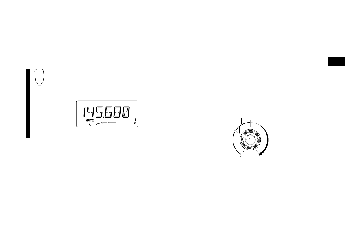
■ Audio mute function
This function temporarily mutes the audio without disturbing
the volume setting.
➥ Push [FUNC] then [
SQL
Y D(MUTE)] to mute
audio signals.
•“MUTE” appears.
• Push [
CLR
A(MW)] (or any other key) to cancel the
function.
■ Squelch attenuator
The transceiver has an RF attenuator related to the squelch
level setting. Approx. 10 dB attenuation is obtained at maximum setting.
➥ Rotate [SQL] clockwise past the 12 o’clock position to ac-
tivate the squelch attenuator.
• Attenuation level can be adjusted up to 10 dB (approx.) between
12 o’clock and fully clockwise position.
• When setting the squelch from the microphone, a level greater
than ‘19’ activates the squelch attenuator.
Squelch is
open.
Squelch
attenuator
Squelch
threshold
Shallow Deep
Noise squelch
15
3 BASIC OPERATION
■ Transmitting
☞ NOTE: To prevent interference, listen on the channel be-
fore transmitting by pushing [MONI(ANM)], or
[
MONI
1(ANM)] on the microphone.
q Set the operating frequency. (pgs. 9, 10)
• Select output power if desired. See section at right for details.
w Push and hold [PTT] to transmit.
•“$” appears.
• The S/RF indicator shows the output power selection.
• A one-touch PTT function is available. See p. 16 for details.
e Speak into the microphone using your normal voice level.
• DO NOT hold the microphone too close to your mouth or speak
too loudly. This may distort the signal.
r Release [PTT] to return to receive.
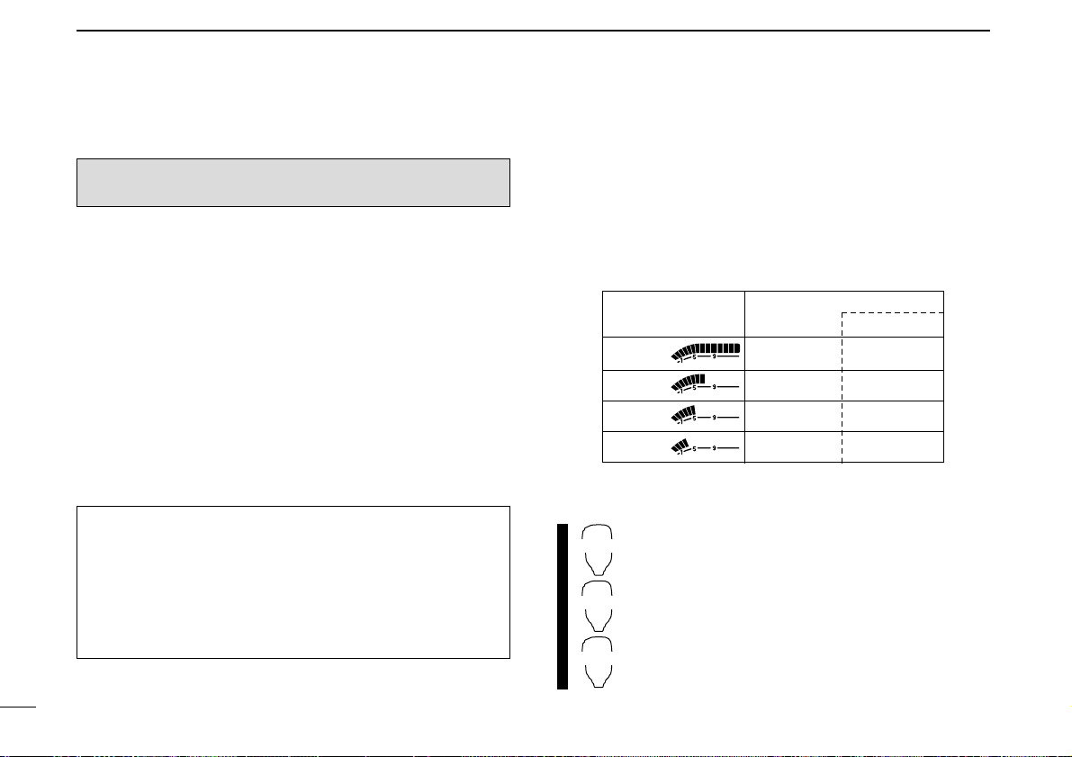
■ Selecting output power
The transceiver has 4* output power levels to suit your operating requirements. Low output powers during short-distance
communications may reduce the possibility of interference to
other stations and will reduce current consumption.
*The Taiwan version has only 3 levels.
Push [LOW(DUP)] several times to select the output power.
• The output power can be changed while transmitting. *approx.
The microphone can also be used to select output power.
➥ Push [
HIGH
4(DTCS)] for high output power;
[
MID
5(DTCSS)] for middle output power; and
[
LOW
6(DTMF)] for low output power.
• The output power can be changed via the microphone
during receive only.
IMPORTANT! (for 75 W transmission):
The IC-V8000 is equipped with protection circuit to protect
the power amplifier circuit from high SWR
(Standing Wave
Ratio) and temperature. When a high SWR antenna or no
antenna is connected, or when the transceiver temperature
becomes extremely high, the transceiver reduces transmit
output power to 25 W (approx.) automatically.
CAUTION: Transmitting without an antenna will damage
the transceiver.
S/RF INDICATOR
POWER OUTPUT
Taiwan
75 W 24 W
25 W* 10 W*
10 W* N/A
5W* 5W*
High:
Mid.:
Mid. Low:
Low:

16
3
BASIC OPERATION
3
■ One-touch PTT function
The PTT switch can be operated as a one-touch PTT switch
(each push switches between transmit/receive). Using this
function you can transmit without pushing and holding the
PTT switch.
To prevent accidental, continuous transmissions with this
function, the transceiver has a time-out timer. See p. 63 for
details.
z Push [FUNC] then [
PRIO
3(PTT-M)] to turn the
one-touch PTT function ON.
• The activity indicator lights green.
x Push [PTT] to transmit and push again to re-
ceive.
• Two beeps sound when transmission is started and a
long beep sounds when returning to receive.
•“$” flashes when transmitting with the one-touch
PTT function.
c Push [FUNC] then [
PRIO
3(PTT-M)] to turn the
one-touch PTT function OFF.
• The activity indicator goes out.
Loading…