

To reduce the impacts on global warming, the packaging materials of this product
are recyclable and reusable. GIGABYTE works with you to protect the environment.
For more product details, please visit GIGABYTE’s website.
GA-AB350-Gaming 3
User’s Manual
Rev. 1002
12ME-AB35GM3-1002R
Copyright
© 2017 GIGA-BYTE TECHNOLOGY CO., LTD. All rights reserved.
The trademarks mentioned in this manual are legally registered to their respective owners.
Disclaimer
Information in this manual is protected by copyright laws and is the property of GIGABYTE.
Changes to the specications and features in this manual may be made by GIGABYTE without prior notice.
No part of this manual may be reproduced, copied, translated, transmitted, or published in any form or
by any means without GIGABYTE’s prior written permission.
For quick set-up of the product, read the Quick Installation Guide included with the product.
In order to assist in the use of this product, carefully read the User’s Manual.
For product-related information, check on our website at: http://www.gigabyte.com
Identifying Your Motherboard Revision
The revision number on your motherboard looks like this: «REV: X.X.» For example, «REV: 1.0″ means
the revision of the motherboard is 1.0. Check your motherboard revision before updating motherboard
BIOS, drivers, or when looking for technical information.
Example:
Motherboard
GA-AB350-Gaming 3
Feb. 6, 2017
Feb. 6, 2017
Motherboard
GA-AB350-Gaming 3

— 3 —
Table of Contents
GA-AB350-Gaming 3 Motherboard Layout ……………………………………………………………4
Chapter 1 Hardware Installation ………………………………………………………………………….5
1-1 Installation Precautions ………………………………………………………………………… 5
1-2 ProductSpecications ………………………………………………………………………….. 6
1-3 Installing the CPU ……………………………………………………………………………….. 9
1-4 Installing the Memory …………………………………………………………………………… 9
1-5 Installing an Expansion Card ………………………………………………………………. 10
1-6 Back Panel Connectors ………………………………………………………………………. 10
1-7 Internal Connectors ……………………………………………………………………………. 12
Chapter 2 BIOS Setup ……………………………………………………………………………………..20
2-1 Startup Screen ………………………………………………………………………………….. 21
2-2 M.I.T. ……………………………………………………………………………………………….. 21
2-3 System …………………………………………………………………………………………….. 25
2-4 BIOS ………………………………………………………………………………………………… 26
2-5 Peripherals ……………………………………………………………………………………….. 29
2-6 Chipset …………………………………………………………………………………………….. 31
2-7 Power ………………………………………………………………………………………………. 32
2-8 Save & Exit ……………………………………………………………………………………….. 34
Chapter 3 Appendix …………………………………………………………………………………………35
3-1 ConguringaRAIDSet ………………………………………………………………………. 35
3-2 DriversInstallation ……………………………………………………………………………… 37
RegulatoryStatements …………………………………………………………………………………. 38
Contact Us …………………………………………………………………………………………………. 40
CPU DRAM
VGA BOOT
— 4 —
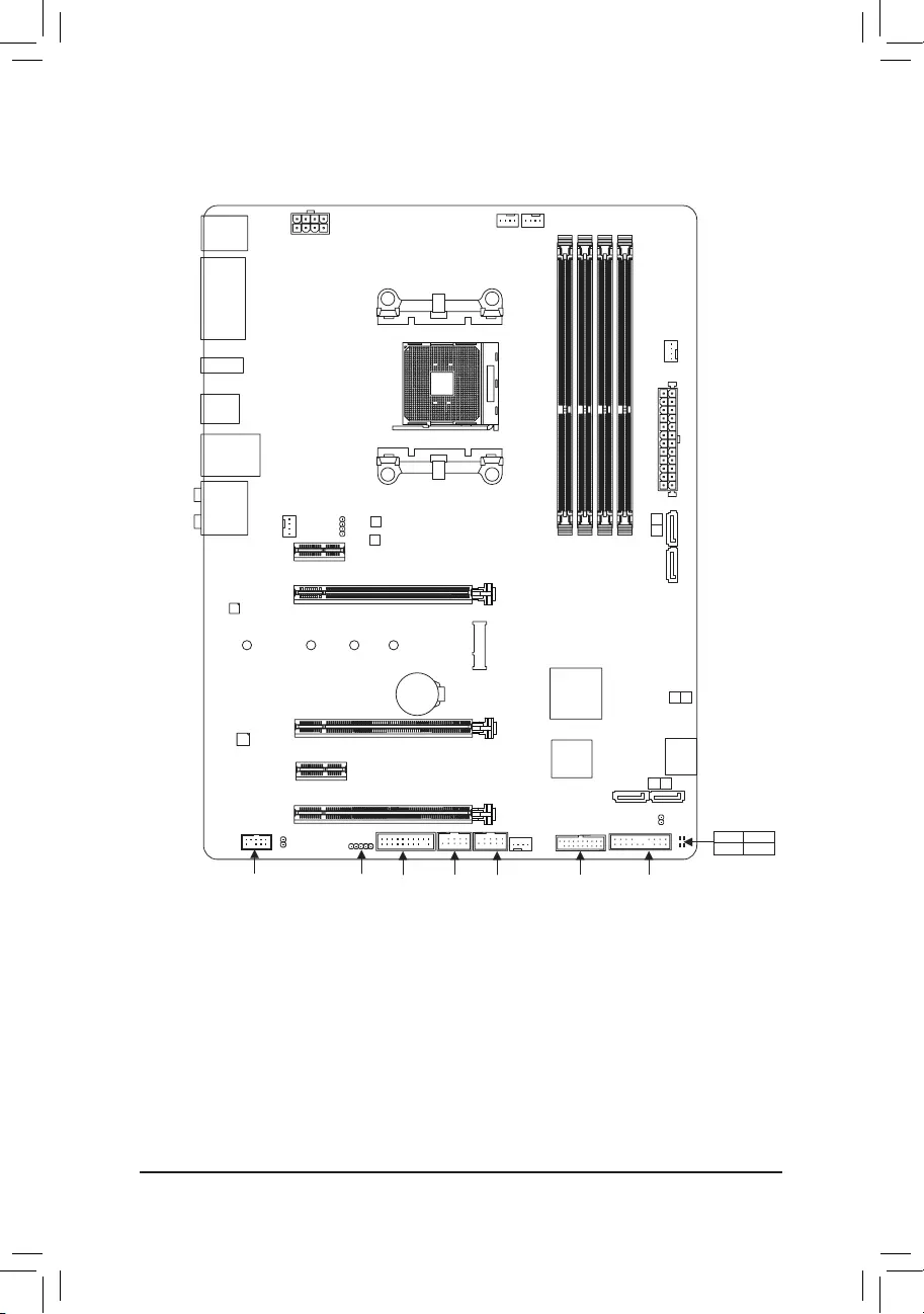
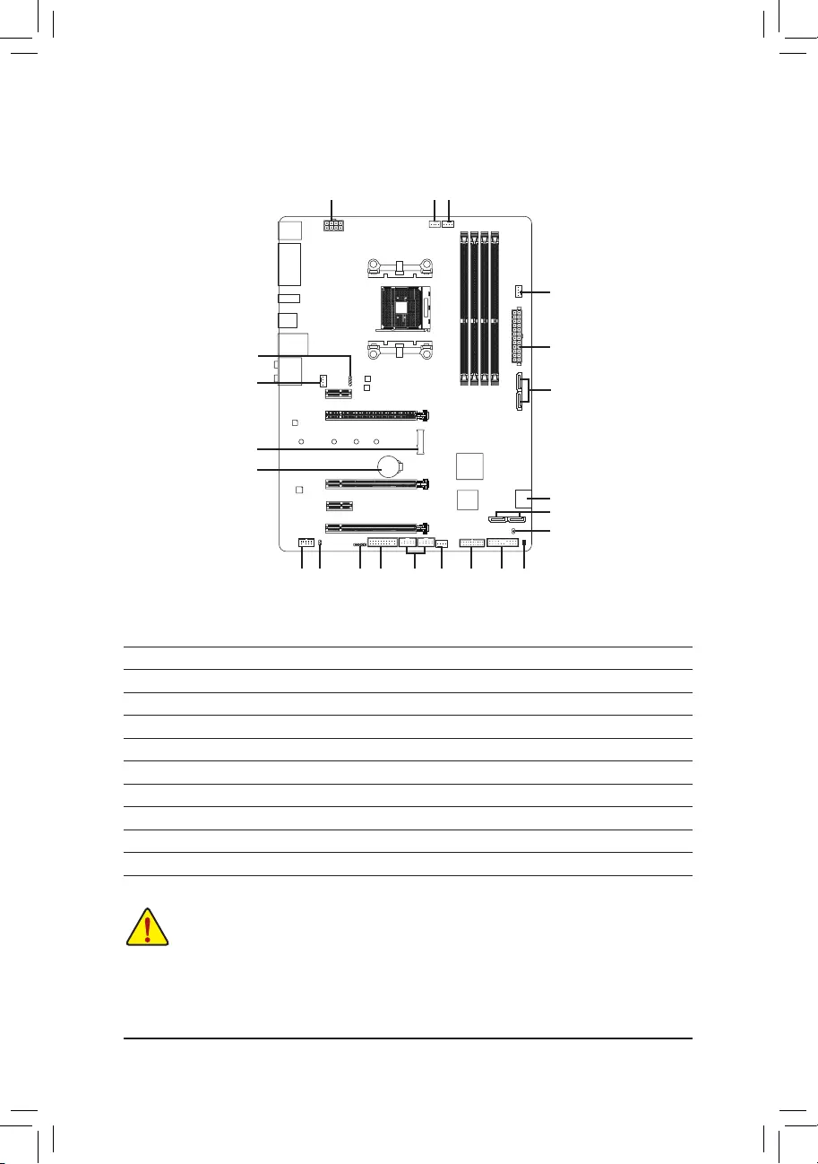
GA-AB350-Gaming 3 Motherboard Layout
Box Contents
5GA-AB350-Gaming 3 motherboard 5Four SATA cables
5Motherboard driver disk 5I/O Shield
5User’s Manual 5One G Connector
5Quick Installation Guide 5OneRGB(RGBW)LEDstripextensioncable
* The box contents above are for reference only and the actual items shall depend on the product package you obtain.
The box contents are subject to change without notice.
Socket AM4
AMDB350
KB_MS_USB3
CPU_FAN
ATX_12V
ATX
F_AUDIO
AUDIO
B_BIOS
PCIEX4
DDR4_2
DDR4_1
DDR4_4
DDR4_3
BAT
F_PANEL
PCIEX1_3
CLR_CMOS
CODEC
M_BIOS
PCIEX1_1
PCIEX16
SPDIF_O
F_USB1
GA-AB350-Gaming 3
DVI
HDMI
USB_DAC
R_USB31
USB30_LAN
SATA3
iTE®
Super I/O
F_USB2
LED_C2
SYS_FAN1
TPM
M2F_32G
Realtek®
GbE LAN
ASATA3 1 0
2
3
F_USB30
SYS_FAN2
42
6080
110
SYS_FAN3_PUMP
CPU_OPT
SATA3 1 0
PCIEX1_2
LED_C1

Chapter 1 Hardware Installation
1-1 Installation Precautions
The motherboard contains numerous delicate electronic circuits and components which can become
damagedasaresultofelectrostaticdischarge(ESD).Priortoinstallation,carefullyreadtheuser’s
manual and follow these procedures:
•Prior to installation, make sure the chassis is suitable for the motherboard.
•Priortoinstallation,donotremoveorbreakmotherboardS/N(SerialNumber)stickeror
warranty sticker provided by your dealer. These stickers are required for warranty validation.
•Always remove the AC power by unplugging the power cord from the power outlet before
installing or removing the motherboard or other hardware components.
•Whenconnectinghardwarecomponentstotheinternalconnectorsonthemotherboard,make
sure they are connected tightly and securely.
•Whenhandlingthemotherboard,avoidtouchinganymetalleadsorconnectors.
•It is best to wear an electrostatic discharge (ESD) wrist strap when handling electronic
componentssuchasamotherboard,CPUormemory.IfyoudonothaveanESDwriststrap,
keepyourhandsdryandrsttouchametalobjecttoeliminatestaticelectricity.
•Prior to installing the motherboard, please have it on top of an antistatic pad or within an
electrostatic shielding container.
•Before connecting or unplugging the power supply cable from the motherboard, make sure
the power supply has been turned off.
•Before turning on the power, make sure the power supply voltage has been set according to
the local voltage standard.
•Before using the product, please verify that all cables and power connectors of your hardware
components are connected.
•To prevent damage to the motherboard, do not allow screws to come in contact with the
motherboard circuit or its components.
•Make sure there are no leftover screws or metal components placed on the motherboard or
within the computer casing.
•Donotplacethecomputersystemonanunevensurface.
•Donotplacethecomputersysteminahigh-temperatureorwetenvironment.
•Turning on the computer power during the installation process can lead to damage to system
components as well as physical harm to the user.
•If you are uncertain about any installation steps or have a problem related to the use of the
product,pleaseconsultacertiedcomputertechnician.
•If you use an adapter, extension power cable, or power strip, ensure to consult with its installation
and/or grounding instructions.
— 5 —
1-2 ProductSpecications
CPU AM4 Socket:
- AMDRyzen™ processor
- AMD7thGenerationA-series/Athlon™ processors
(GotoGIGABYTE’swebsiteforthelatestCPUsupportlist.)
Chipset AMDB350
Memory 4xDDR4DIMMsocketssupportingupto64GBofsystemmemory
* DuetoaWindows32-bitoperatingsystemlimitation,whenmorethan4GBofphysical
memoryisinstalled,theactualmemorysizedisplayedwillbelessthanthesizeof
the physical memory installed.
Dualchannelmemoryarchitecture
SupportforDDR42667(Note)/2400/2133MHzmemorymodules
SupportforECCUn-bufferedDIMM1Rx8/2Rx8memory modules(operate in
non-ECCmode)
Supportfornon-ECCUn-bufferedDIMM1Rx8/2Rx8/1Rx16memorymodules
Support for Extreme Memory Prole (XMP) memory modules
(GotoGIGABYTE’swebsiteforthelatestsupportedmemoryspeedsandmemory
modules.)
Onboard
Graphics
Integrated Graphics Processor:
- 1xDVI-Dport,supportingamaximumresolutionof1920×1200@60Hz
* TheDVI-DportdoesnotsupportD-Subconnectionbyadapter.
- 1xHDMIport,supportingamaximumresolutionof4096×2160@24Hz
* SupportforHDMI1.4version.
— Maximum shared memory of 2 GB
Audio Realtek® ALC1220 codec
HighDenitionAudio
2/4/5.1/7.1-channel
SupportforS/PDIFOut
LAN Realtek®GbELANchip(10/100/1000Mbit)
Expansion Slots 1xPCIExpressx16slot,runningatx16(PCIEX16)(Note)
* For optimum performance, if only one PCI Express graphics card is to be installed,
be sure to install it in the PCIEX16 slot.
(ThePCIEX16slotconformstoPCIExpress3.0standard.)
1xPCIExpressx16slot,runningatx4(PCIEX4)
* The PCIEX4 slot shares bandwidth with the PCIEX1_2 and PCIEX1_3 slots. The
PCIEX4 slot operates at up to x2 mode when the PCIEX1_2/PCIEX1_3 slot is
populated. The PCIEX4 slot operates at up to x4 mode when both of the PCIEX1_2
and PCIEX1_3 slots are empty.
1xPCIExpressx16slot,runningatx1(PCIEX1_3)
2 x PCI Express x1 slots
(ThePCIEX4andPCIExpressx1slotsconformtoPCIExpress2.0standard.))
Multi-Graphics
Technology SupportforAMDQuad-GPUCrossFire™and2-WayAMDCrossFire™ technologies
Storage Interface 1xM.2connector(Socket3,Mkey,type2242/2260/2280/22110SATAandPCIe
x4 (Note)/x2SSDsupport)
6 x SATA 6Gb/s connectors
SupportforRAID0,RAID1,andRAID10
* Referto»1-7InternalConnectors,»fortheinstallationnoticesfortheM.2andSATA
connectors.
(Note) ActualsupportmayvarybyCPU.
— 6 —
USB Chipset:
- 2xUSB3.1Gen2Type-Aports(red)onthebackpanel
— 2xUSB3.1Gen1ports(availablethroughtheinternalUSBheader)
— 5 x USB 2.0/1.1 ports (1portonthebackpanel,4portsavailablethrough
theinternalUSBheaders)
CPU:
— 4 x USB 3.1 Gen 1 ports on the back panel
Internal
Connectors
1 x 24-pin ATX main power connector
1 x 8-pin ATX 12V power connector
1 x M.2 Socket 3 connector
6 x SATA 6Gb/s connectors
1 x CPU fan header
1 x water cooling CPU fan header
2 x system fan headers
1 x system fan/water cooling pump header
1 x front panel header
1 x front panel audio header
1xS/PDIFOutheader
1 x USB 3.1 Gen 1 header
2 x USB 2.0/1.1 headers
1xTrustedPlatformModule(TPM)header
1xCPUcoolerLEDstrip/RGBLEDstripextensioncableheader
1xRGB(RGBW)LEDstripextensioncableheader
1 x Clear CMOS jumper
Back Panel
Connectors
1 x PS/2 keyboard/mouse port
1xDVI-Dport
1xHDMIport
4 x USB 3.1 Gen 1 ports
2xUSB3.1Gen2Type-Aports(red)
1 x USB 2.0/1.1 port
1xRJ-45port
1xopticalS/PDIFOutconnector
5xaudiojacks (Center/Subwoofer SpeakerOut,Rear Speaker Out,LineIn,
LineOut,MicIn)
I/O Controller iTE® I/O Controller Chip
Hardware
Monitor
Voltage detection
Temperature detection
Fan speed detection
Overheating warning
Fan fail warning
Fan speed control
* Whetherthefan(pump)speedcontrolfunctionissupportedwilldependonthefan
(pump)youinstall.
— 7 —
BIOS 2x128Mbitash
Use of licensed AMI UEFI BIOS
SupportforDualBIOS™
PnP1.0a,DMI2.7,WfM2.0,SMBIOS2.7,ACPI5.0
Unique Features Support for APP Center
* Available applications in APP Center may vary by motherboard model. Supported
functionsofeachapplicationmayalsovarydependingonmotherboardspecications.
- @BIOS
- 3DOSD
— AutoGreen
— BIOS Setup
— Cloud Station
— Color Temperature
— EasyTune
— Fast Boot
— Game Boost
— ON/OFF Charge
- RGBFusion
— Smart Backup
— Smart Keyboard
— Smart TimeLock
— System Information Viewer
— USB Blocker
- USBDACUP2
— V-Tuner
Support for Q-Flash
Support for Xpress Install
Bundled
Software
Norton®InternetSecurity(OEMversion)
cFosSpeed
Operating
System
SupportforWindows1064-bit
SupportforWindows764-bit
* Pleasedownloadthe«WindowsUSBInstallationTool»fromGIGABYTE’swebsite
andinstallitbeforeinstallingWindows7.
Form Factor ATX Form Factor; 30.5cm x 23.0cm
* GIGABYTEreservestherighttomakeanychangestotheproductspecicationsandproduct-relatedinformationwithout
prior notice.
Please visit GIGABYTE’s website
for support lists of CPU, memory
modules,SSDs,andM.2devices..
Please visit the Support\Utility List
page on GIGABYTE’s website to
download the latest version of apps.
— 8 —
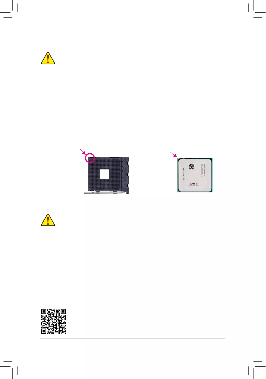
1-3 Installing the CPU
Installing the CPU
Locatethepinone(denotedbyasmalltriangle)oftheCPUsocketandtheCPU.
AM4 Socket
A Small Triangle Marking
DenotesPinOneofthe
Socket AM4 CPU
A Small Triangle Marking
DenotesCPUPinOne
1-4 Installing the Memory
DualChannelMemoryConguration
ThismotherboardprovidesfourmemorysocketsandsupportsDualChannelTechnology.Afterthememory
isinstalled,theBIOSwillautomaticallydetectthespecicationsandcapacityofthememory.EnablingDual
Channel memory mode will double the original memory bandwidth.
The four memory sockets are divided into two channels and each channel has two memory sockets as following:
ChannelA:DDR4_2,DDR4_4
ChannelB:DDR4_1,DDR4_3
Readthefollowingguidelinesbeforeyoubegintoinstallthememory:
•Make sure that the motherboard supports the memory. It is recommended that memory of the
same capacity, brand, speed, and chips be used.
(GotoGIGABYTE’swebsiteforthelatestsupportedmemoryspeedsandmemorymodules.)
•Always turn off the computer and unplug the power cord from the power outlet before installing the
memory to prevent hardware damage.
•Memory modules have a foolproof design. A memory module can be installed in only one direction.
If you are unable to insert the memory, switch the direction.
ReadthefollowingguidelinesbeforeyoubegintoinstalltheCPU:
•Make sure that the motherboard supports the CPU.
(GotoGIGABYTE’swebsiteforthelatestCPUsupportlist.)
•Always turn off the computer and unplug the power cord from the power outlet before installing the
CPU to prevent hardware damage.
•LocatethepinoneoftheCPU.TheCPUcannotbeinsertediforientedincorrectly.(Oryoumay
locatethenotchesonbothsidesoftheCPUandalignmentkeysontheCPUsocket.)
•Apply an even and thin layer of thermal grease on the surface of the CPU.
•DonotturnonthecomputeriftheCPUcoolerisnotinstalled,otherwiseoverheatinganddamage
of the CPU may occur.
•SettheCPUhostfrequencyinaccordancewiththeCPUspecications.Itisnotrecommended
thatthesystembusfrequencybesetbeyondhardwarespecicationssinceitdoesnotmeetthe
standard requirements for the peripherals. If you wish to set the frequency beyond the standard
specications,pleasedosoaccordingtoyourhardwarespecicationsincludingtheCPU,graphics
card, memory, hard drive, etc.
Please visit GIGABYTE’s website for details on hardware installation.
— 9 —
1-5 Installing an Expansion Card
Readthefollowingguidelinesbeforeyoubegintoinstallanexpansioncard:
•Make sure the motherboard supports the expansion card. Carefully read the manual that came
with your expansion card.
•Always turn off the computer and unplug the power cord from the power outlet before installing an
expansion card to prevent hardware damage.
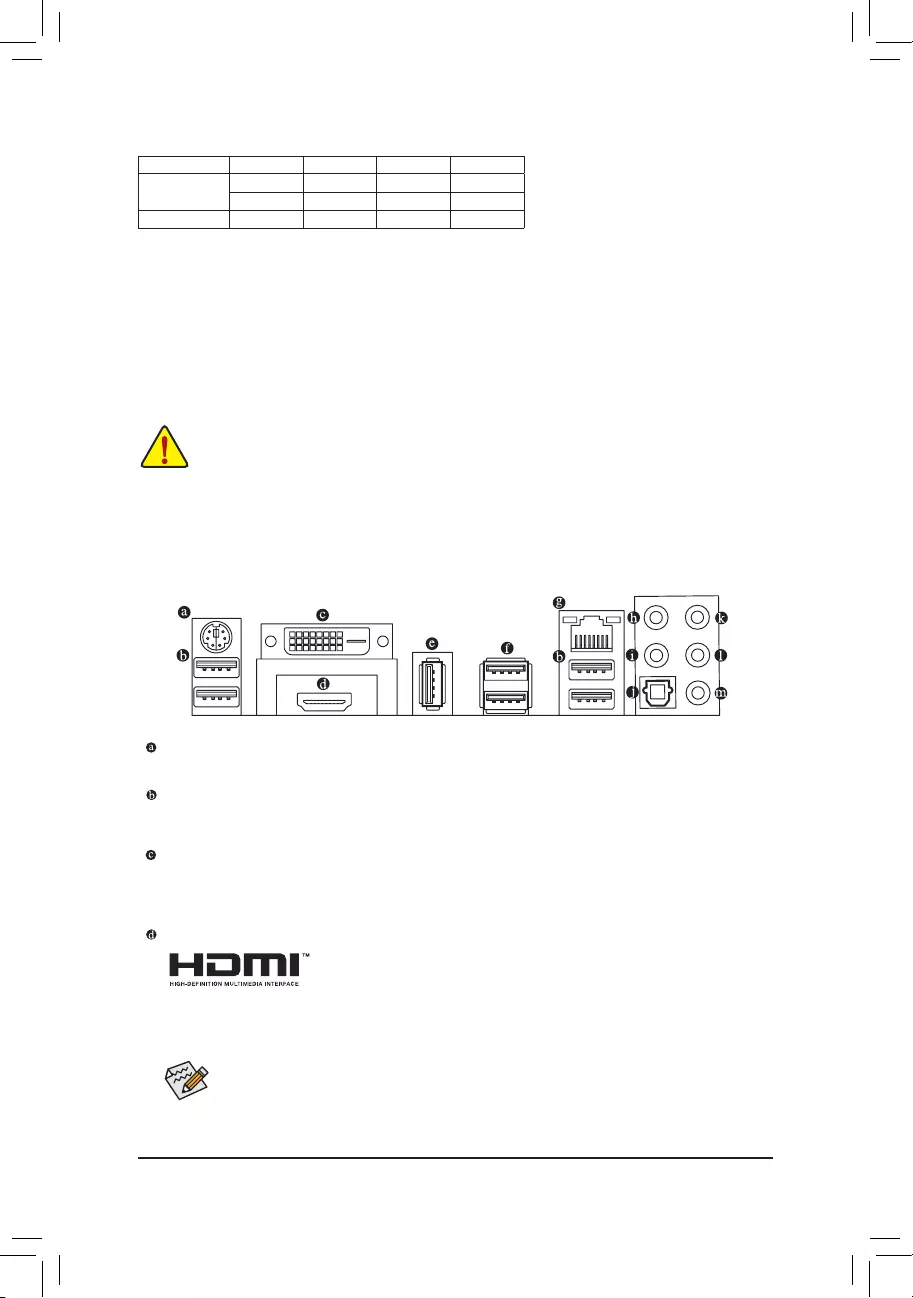
PS/2 Keyboard/Mouse Port
Use this port to connect a PS/2 mouse or keyboard.
USB 3.1 Gen 1 Port
TheUSB3.1Gen1portsupportstheUSB3.1Gen1specicationandiscompatibletotheUSB2.0
specication.UsethisportforUSBdevices.
DVI-D Port (Note)
TheDVI-DportconformstotheDVI-Dspecicationandsupportsamaximumresolutionof1920×1200@60Hz
(theactualresolutionssupporteddependonthemonitorbeingused).Connectamonitorthatsupports
DVI-Dconnectiontothisport.
HDMI Port
TheHDMIportisHDCPcompliantandsupportsDolbyTrueHDandDTSHD
MasterAudio formats.Italsosupportsupto192 KHz/24bit8-channel LPCM
audiooutput.YoucanusethisporttoconnectyourHDMI-supportedmonitor.Themaximumsupported
resolutionis4096×2160@24 Hz,buttheactual resolutionssupportedaredependent onthemonitor
being used.
1-6 Back Panel Connectors
AfterinstallingtheHDMIdevice,makesuretosetthedefaultsoundplaybackdevicetoHDMI.(The
itemnamemaydifferdependingonyouroperatingsystem.)
DualChannelMemoryCongurationsTable
DDR4_4 DDR4_2 DDR4_3 DDR4_1
Two Modules — — DS/SS — — DS/SS
DS/SS — — DS/SS — —
Four Modules DS/SS DS/SS DS/SS DS/SS
(SS=Single-Sided,DS=Double-Sided,»--«=NoMemory)
(Note) TheDVI-DportdoesnotsupportD-Subconnectionbyadapter.
DuetoCPUlimitations,readthefollowingguidelinesbeforeinstallingthememoryinDualChannelmode.
1. DualChannelmodecannotbeenabledifonlyonememorymoduleisinstalled.
2. WhenenablingDualChannelmodewithtwoorfourmemorymodules,itisrecommendedthatmemory
of the same capacity, brand, speed, and chips be used. For optimum performance, when enabling
DualChannelmodewithtwomemorymodules,werecommendthatyouinstallthemintheDDR4_1
andDDR4_2sockets.
— 10 —
•Whenremovingthecableconnectedtoabackpanelconnector,rstremovethecablefromyour
device and then remove it from the motherboard.
•Whenremovingthecable,pullitstraightoutfromtheconnector.Donotrockitsidetosidetoprevent
an electrical short inside the cable connector.
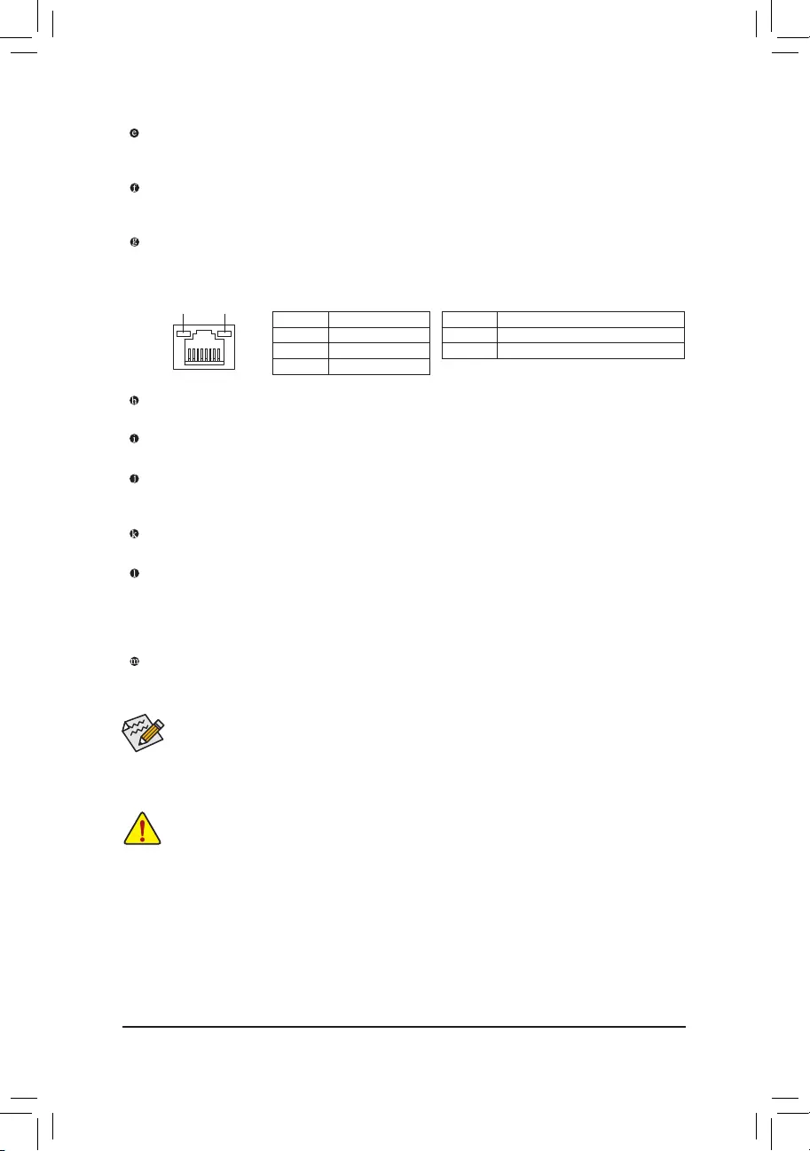
ActivityLED
Connection/
SpeedLED
LAN Port
ActivityLED:Connection/SpeedLED:
State Description
Orange 1 Gbps data rate
Green 100 Mbps data rate
Off 10 Mbps data rate
State Description
Blinking Datatransmissionorreceivingisoccurring
Off No data transmission or receiving is occurring
Center/Subwoofer Speaker Out
Usethisaudiojacktoconnectcenter/subwooferspeakersina5.1/7.1-channelaudioconguration.
Rear Speaker Out
Thisjackcanbeusedtoconnectrearspeakersina4/5.1/7.1-channelaudioconguration.
Optical S/PDIF Out Connector
This connector provides digital audio out to an external audio system that supports digital optical audio.
Before using this feature, ensure that your audio system provides an optical digital audio in connector.
Line In
The line in jack. Use this audio jack for line in devices such as an optical drive, walkman, etc.
Line Out
The line out jack. This jack supports audio amplifying function. For better sound quality, it is recommended
thatyouconnectyourheadphone/speakertothisjack(actualeffectsmayvarybythedevicebeingused).
Use this audio jack for a headphone or 2-channel speaker. This jack can be used to connect front speakers
ina4/5.1/7.1-channelaudioconguration.
Mic In
The Mic in jack.
USB 2.0/1.1 Port
TheUSBportsupportstheUSB2.0/1.1specication.YoucanconnectaUSBDACtothisportoruse
this port for USB devices.
USB 3.1 Gen 2 Type-A Port (Red)
TheUSB3.1Gen2Type-AportsupportstheUSB3.1Gen2specicationandiscompatibletotheUSB
3.1Gen1andUSB2.0specication.UsethisportforUSBdevices.
RJ-45 LAN Port
The Gigabit Ethernet LAN port provides Internet connection at up to 1 Gbps data rate. The following
describesthestatesoftheLANportLEDs.
•ToenableorconguretheaudioamplifyingfunctionfortheLineoutjack,pleaseaccesstheHD
Audio Manager application.
•If you want to install a Side Speaker, you need to retask either the Line in or Mic in jack to be Side
SpeakeroutusingtheHDAudioManagerapplication.
•Please visit GIGABYTE’s website for more audio software information.
— 11 —
1-7 Internal Connectors
Readthefollowingguidelinesbeforeconnectingexternaldevices:
•First make sure your devices are compliant with the connectors you wish to connect.
•Before installing the devices, be sure to turn off the devices and your computer. Unplug the power
cord from the power outlet to prevent damage to the devices.
•After installing the device and before turning on the computer, make sure the device cable has
been securely attached to the connector on the motherboard.
1) ATX_12V
2) ATX
3) CPU_FAN
4) SYS_FAN1/2
5) CPU_OPT
6) SYS_FAN3_PUMP
7) ASATA3 0/1
 SATA3 0/1/2/3
9) M2F_32G
10) SPDIF_O
11) F_PANEL
12) F_AUDIO
13) BAT
14) CLR_CMOS
15) F_USB30
16) F_USB1/F_USB2
17) TPM
18) CPU/VGA/DRAM/BOOT
19) LED_C1
20) LED_C2
1
2
3
11
6
20
4
9
7
16
14
10
4
5
8
8
12 15
17
13
18
19
— 12 —
131
2412
ATX
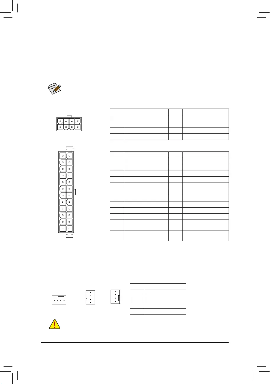
1/2) ATX_12V/ATX (2×4 12V Power Connector and 2×12 Main Power Connector)
Withtheuseofthepowerconnector,thepowersupplycansupplyenoughstablepowertoallthecomponents
onthemotherboard.Beforeconnectingthepowerconnector,rstmakesurethepowersupplyisturned
off and all devices are properly installed. The power connector possesses a foolproof design. Connect the
power supply cable to the power connector in the correct orientation.
The 12V power connector mainly supplies power to the CPU. If the 12V power connector is not connected,
the computer will not start.
To meet expansion requirements, it is recommended that a power supply that can withstand high
powerconsumptionbeused(500Worgreater).Ifapowersupplyisusedthatdoesnotprovidethe
required power, the result can lead to an unstable or unbootable system.
ATX:
Pin No. Denition Pin No. Denition
1 3.3V 13 3.3V
2 3.3V 14 -12V
3GND 15 GND
4 +5V 16 PS_ON(softOn/Off)
5GND 17 GND
6 +5V 18 GND
7GND 19 GND
8 Power Good 20 NC
95VSB(standby+5V) 21 +5V
10 +12V 22 +5V
11 +12V(Onlyfor 2×12-pin
ATX)
23 +5V(Onlyfor2×12-pinATX)
12 3.3V(Onlyfor2×12-pin
ATX)
24 GND(Onlyfor2×12-pinATX)
ATX_12V:
Pin No. Denition Pin No. Denition
1GND(Onlyfor2×4-pin12V) 5+12V(Onlyfor2×4-pin12V)
2GND(Onlyfor2×4-pin12V) 6+12V(Onlyfor2×4-pin12V)
3GND 7 +12V
4GND 8 +12V
ATX_12V
8
4
5
1
3/4) CPU_FAN/SYS_FAN1/2 (Fan Headers)
All fan headers on this motherboard are 4-pin. Most fan headers possess a foolproof insertion design.
Whenconnectingafancable,besuretoconnectitinthecorrectorientation(theblackconnectorwireis
thegroundwire).Thespeedcontrolfunctionrequirestheuseofafanwithfanspeedcontroldesign.For
optimum heat dissipation, it is recommended that a system fan be installed inside the chassis.
CPU_FAN
1
Pin No. Denition
1GND
2 Voltage Speed Control
3 Sense
4PWMSpeedControl
1
1
SYS_FAN2
SYS_FAN1
•Be sure to connect fan cables to the fan headers to prevent your CPU and system from
overheating. Overheating may result in damage to the CPU or the system may hang.
•Thesefanheadersarenotcongurationjumperblocks.Donotplaceajumpercapontheheaders.
— 13 —
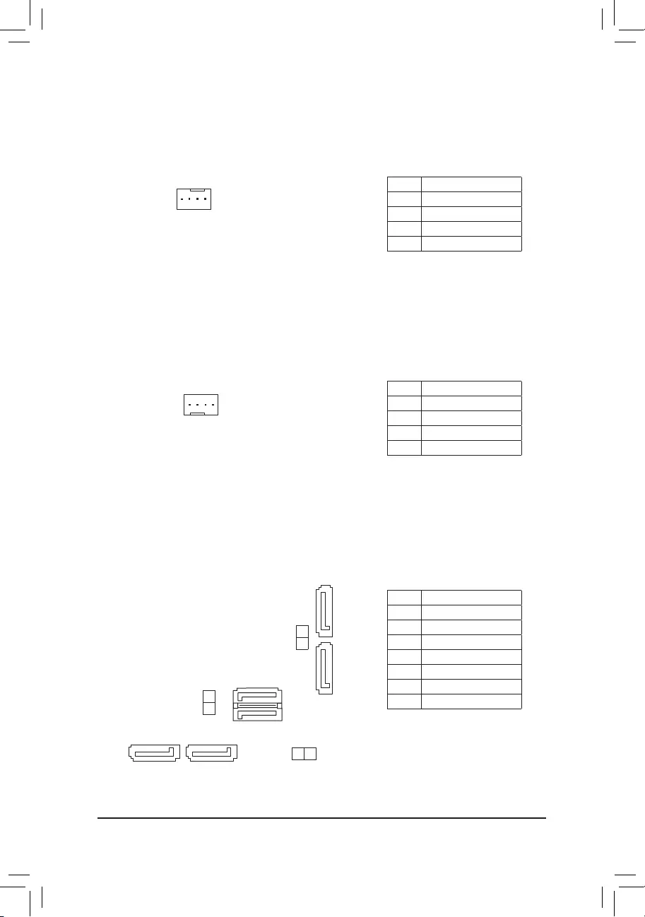
5) CPU_OPT (Water Cooling CPU Fan Header)
The fan header is 4-pin and possesses a foolproof insertion design. Most fan headers possess a foolproof
insertiondesign.Whenconnectingafancable,besuretoconnectitinthecorrectorientation(theblack
connectorwireisthegroundwire).Thespeedcontrolfunctionrequirestheuseofafanwithfanspeed
control design.
Pin No. Denition
1GND
2 Voltage Speed Control
3 Sense
4PWMSpeedControl
1
6) SYS_FAN3_PUMP (System Fan/Water Cooling Pump Headers)
Thefan/pumpheadersare4-pin.Mostfanheaderspossessafoolproofinsertiondesign.Whenconnecting
afancable,besuretoconnectitinthecorrectorientation(theblackconnectorwireisthegroundwire).
The speed control function requires the use of a fan with fan speed control design. For optimum heat
dissipation, it is recommended that a system fan be installed inside the chassis. The headers also provides
speedcontrolforawatercoolingpump,refertoChapter2,»BIOSSetup,»»M.I.T.,»formoreinformation
1
Pin No. Denition
1GND
2 Voltage Speed Control
3 Sense
4PWMSpeedControl
7/8) ASATA3 0/1, SATA3 0/1/2/3 (SATA 6Gb/s Connectors)
The SATA connectors conform to SATA 6Gb/s standard and are compatible with SATA 3Gb/s and SATA
1.5Gb/s standard. Each SATA connector supports a single SATA device. The SATA connectors support
RAID0,RAID1,andRAID10.RefertoChapter3,«ConguringaRAIDSet,»forinstructionsonconguring
aRAIDarray.
Pin No. Denition
1GND
2 TXP
3 TXN
4GND
5RXN
6RXP
7GND
SATA3 2
3
71
7
1
7 1
7 1
SATA3 1 0
ASATA3 0
1
— 14 —
9) M2F_32G (M.2 Socket 3 Connector)
TheM.2connectorsupportsM.2SATASSDsandM.2PCIeSSDsandsupportsSATARAIDconguration
throughtheAMDChipset.PleasenotethatanM.2PCIeSSDcannotbeusedtocreateaRAIDarray.Refer
toChapter3,»ConguringaRAIDSet,»forinstructionsonconguringaRAIDarray.
F_USB30 F_U
B_
F_ F_
_
B
BS_
B
SB_
B
_S
S_
_
B
_U
_
B
S
123
123
123
123
1
1
1
1
BSS
S
_S
SSU
1 2 3
S3 BSSS
U
__ 3
F_USB3F
S _
S _
S _
SF
B_
B_
F
_0
S
S
_0F
_F
_
_
__B
U
S _S
_
USB0_B
B_ F_USB3
80110 60 42
SelecttheproperholefortheM.2SSDtobeinstalledandrefastenthescrewandnut.
FollowthestepsbelowtocorrectlyinstallanM.2SSDintheM.2connector.
Step 1:
Use a screw driver to unfasten the screw and nut from the motherboard. Locate the proper mounting hole
fortheM.2SSDtobeinstalledandthenscrewthenutrst.
Step 2:
SlidetheM.2SSDintotheconnectoratanangle.
Step 3:
PresstheM.2SSDdownandthensecureitwiththescrew.
SATA3 0 SATA3 1 SATA3 2 SATA3 3 ASATA3 0 ASATA3 1
M.2SATASSD a a a r a a
M.2PCIex4SSD*
a a a a r r
M.2PCIex2SSD
aaaaaa
NoM.2SSDInstalled aaaaaa
a: Available, r: Not available
* ForAMDRyzen™ processor only.
Connector
Type of
M.2SSD
Installation Notices for the M2F_32G and SATA Connectors:
DuetothelimitednumberoflanesprovidedbytheChipset,theavailabilityoftheSATAconnectorsmaybe
affectedbythetypeofdevicesinstalledintheM2F_32Gconnector.Refertothefollowingtablefordetails.
— 15 —
10) SPDIF_O (S/PDIF Out Header)
ThisheadersupportsdigitalS/PDIFOutandconnectsaS/PDIFdigitalaudiocable(providedbyexpansion
cards)fordigitalaudiooutputfromyourmotherboardtocertainexpansioncardslikegraphicscardsand
soundcards.Forexample,somegraphicscardsmayrequireyoutouseaS/PDIFdigitalaudiocablefor
digitalaudiooutputfromyourmotherboardtoyourgraphicscardifyouwishtoconnectanHDMIdisplay
tothegraphicscardandhavedigitalaudiooutputfromtheHDMIdisplayatthesametime.Forinformation
aboutconnectingtheS/PDIFdigitalaudiocable,carefullyreadthemanualforyourexpansioncard.
Pin No. Denition
1SPDIFO
2GND
1
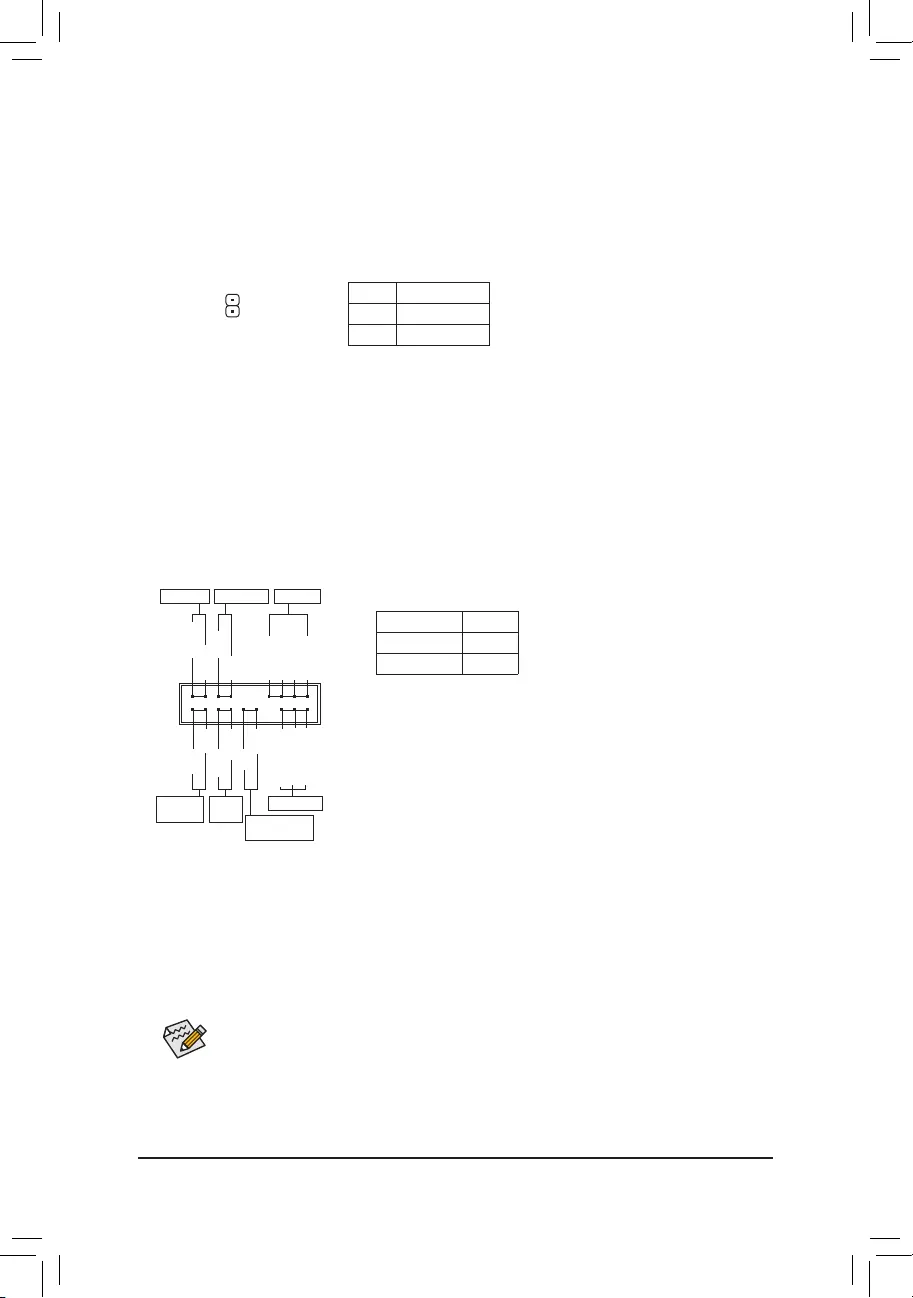
11) F_PANEL (Front Panel Header)
Connect the power switch, reset switch, speaker, chassis intrusion switch/sensor and system status indicator
on the chassis to this header according to the pin assignments below. Note the positive and negative pins
before connecting the cables.
System Status LED
S0 On
S3/S4/S5 Off
•PW(PowerSwitch,Red):
Connects to the power switch on the chassis front panel. You may
congurethewaytoturnoffyoursystemusingthepowerswitch(refer
toChapter2,»BIOSSetup,»»Power,»formoreinformation).
•SPEAK (Speaker,Orange):
Connects to the speaker on the chassis front panel. The system reports
system startup status by issuing a beep code. One single short beep
will be heard if no problem is detected at system startup.
•PLED/PWR_LED (PowerLED,Yellow/Purple):
Connects to the power status indicator
onthechassisfrontpanel.TheLEDison
whenthesystemisoperating.TheLEDis
off when the system is in S3/S4 sleep state
orpoweredoff(S5).
•HD (HardDriveActivityLED,Blue):
ConnectstotheharddriveactivityLEDonthechassisfrontpanel.TheLEDisonwhentheharddriveis
reading or writing data.
•RES (ResetSwitch,Green):
Connects to the reset switch on the chassis front panel. Press the reset switch to restart the computer if the
computerfreezesandfailstoperformanormalrestart.
•CI (ChassisIntrusionHeader,Gray):
Connects to the chassis intrusion switch/sensor on the chassis that can detect if the chassis cover has been
removed. This function requires a chassis with a chassis intrusion switch/sensor.
•NC (Orange):NoConnection.
NC
NC
PowerLED
1
2
19
20
CI-
CI+
PWR_LED-
PWR_LED+
PLED-
PW-
SPEAK+
SPEAK-
PLED+
PW+
PowerLED
HD-
RES+
HD+
RES-
HardDrive
ActivityLED
Reset
Switch Chassis Intrusion
Header
Power Switch Speaker
PWR_LED-
The front panel design may differ by chassis. A front panel module mainly consists of power switch,
resetswitch,powerLED,harddriveactivityLED,speakerandetc.Whenconnectingyourchassis
front panel module to this header, make sure the wire assignments and the pin assignments are
matched correctly.
— 16 —
12) F_AUDIO (Front Panel Audio Header)
ThefrontpanelaudioheadersupportsIntelHighDenitionaudio(HD)andAC’97audio.Youmayconnect
your chassis front panel audio module to this header. Make sure the wire assignments of the module
connector match the pin assignments of the motherboard header. Incorrect connection between the module
connector and the motherboard header will make the device unable to work or even damage it.
ForHDFrontPanelAudio: For AC’97 Front Panel Audio:
•ThefrontpanelaudioheadersupportsHDaudiobydefault.
•Audio signals will be present on both of the front and back panel audio connections simultaneously.
•Some chassis provide a front panel audio module that has separated connectors on each wire
instead of a single plug. For information about connecting the front panel audio module that has
different wire assignments, please contact the chassis manufacturer.
Pin No. Denition
1 MIC2_L
2GND
3MIC2_R
4 NC
5LINE2_R
6 Sense
7FAUDIO_JD
8 No Pin
9 LINE2_L
10 Sense
Pin No. Denition
1 MIC
2GND
3 MIC Power
4 NC
5LineOut(R)
6 NC
7 NC
8 No Pin
9LineOut(L)
10 NC
F_USB30 F_U
B_
F_ F_
_
B
BS_
B
SB_
B
_S
S_
_
B
_U
_
B
S
123
123
123
123
1
1
1
1
BSS
S
_S
SSU
1 2 3
S3 BSSS
U
__ 3
F_USB3F
S _
S _
S _
SF
B_
B_
F
_0
S
S
_0F
_F
_
_
__B
U
S _S
_
USB0_B
B_ F_USB3
9 1
10 2
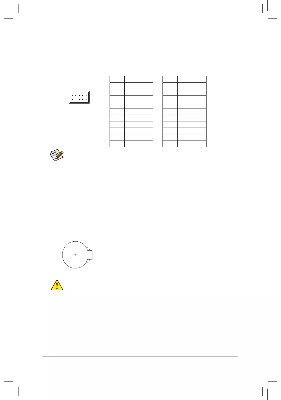
13) BAT (Battery)
Thebatteryprovidespowertokeepthevalues(suchasBIOScongurations,date,andtimeinformation)
intheCMOSwhenthecomputeristurnedoff.Replacethebatterywhenthebatteryvoltagedropstoalow
level, or the CMOS values may not be accurate or may be lost.
You may clear the CMOS values by removing the battery:
1. Turn off your computer and unplug the power cord.
2. Gently remove the battery from the battery holder and wait for one minute.
(Oruseametalobjectlikeascrewdrivertotouchthepositiveandnegative
terminalsofthebatteryholder,makingthemshortfor5seconds.)
3. Replacethebattery.
4. Plug in the power cord and restart your computer.
•Always turn off your computer and unplug the power cord before replacing the battery.
•Replacethebatterywithanequivalentone.Dangerofexplosionifthebatteryisreplacedwith
an incorrect model.
•Contact the place of purchase or local dealer if you are not able to replace the battery by yourself
or uncertain about the battery model.
•Wheninstallingthebattery,notetheorientationofthepositiveside(+)andthenegativeside(-)
ofthebattery(thepositivesideshouldfaceup).
•Used batteries must be handled in accordance with local environmental regulations.
— 17 —
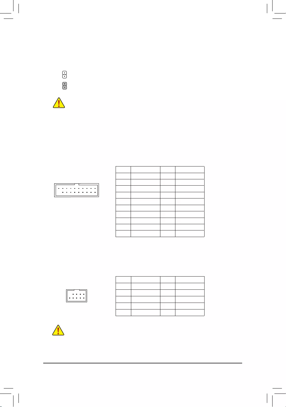
16) F_USB1/F_USB2 (USB 2.0/1.1 Headers)
TheheadersconformtoUSB2.0/1.1specication.EachUSBheadercanprovidetwoUSBportsviaan
optional USB bracket. For purchasing the optional USB bracket, please contact the local dealer.
Pin No. Denition Pin No. Denition
1Power(5V) 6USBDY+
2Power(5V) 7GND
3USBDX- 8GND
4USBDY— 9 No Pin
5USBDX+ 10 NC
•DonotplugtheIEEE1394bracket(2×5-pin)cableintotheUSB2.0/1.1header.
•Prior to installing the USB bracket, be sure to turn off your computer and unplug the power cord
from the power outlet to prevent damage to the USB bracket.
10
9
2
1
Pin No. Denition Pin No. Denition
1 VBUS 11 D2+
2SSRX1- 12 D2-
3SSRX1+ 13 GND
4GND 14 SSTX2+
5 SSTX1- 15 SSTX2-
6 SSTX1+ 16 GND
7GND 17 SSRX2+
8D1- 18 SSRX2-
9D1+ 19 VBUS
10 NC 20 No Pin
15) F_USB30 (USB 3.1 Gen 1 Header)
The header conforms to USB 3.1 Gen 1 and USB 2.0 specication and can provide two USB ports. For
purchasing the optional 3.5« front panel that provides two USB 3.1 Gen 1 ports, please contact the local
dealer.
F_USB30 F_U
B_
F_ F_
_
B
BS_
B
SB_
B
_S
S_
_
B
_U
_
B
S
123
123
123
123
1
1
1
1
BSS
S
_S
SSU
1 2 3
S3 BSSS
U
__ 3
F_USB3F
S _
S _
S _
SF
B_
B_
F
_0
S
S
_0F
_F
_
_
__B
U
S _S
_
USB0_B
B_ F_USB3
10
20
1
11
14) CLR_CMOS (Clear CMOS Jumper)
UsethisjumpertocleartheBIOScongurationandresettheCMOSvaluestofactorydefaults.Toclear
the CMOS values, use a metal object like a screwdriver to touch the two pins for a few seconds.
•Always turn off your computer and unplug the power cord from the power outlet before clearing
the CMOS values.
•Aftersystemrestart,gotoBIOSSetuptoloadfactorydefaults(selectLoadOptimizedDefaults)or
manuallyconguretheBIOSsettings(refertoChapter2,«BIOSSetup,»forBIOScongurations).
Open: Normal
Short: Clear CMOS Values
— 18 —
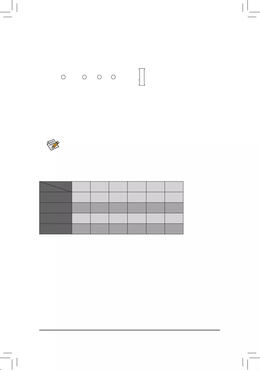
18) CPU/VGA/DRAM/BOOT (Status LEDs)
Thestatus LEDs show whether the CPU, graphicscard, memory,and operating system are working
properlyaftersystempower-on.IftheCPU/VGA/DRAMLEDison,thatmeansthecorrespondingdevice
isnotworkingnormally;iftheBOOTLEDison,thatmeansyouhaven’tenteredtheoperatingsystemyet.
F_USB30 F_U
B_
F_ F_
_
B
BS_
B
SB_
B
_S
S_
_
B
_U
_
B
S
123
123
123
123
1
1
1
1
BSS
S
_S
SSU
1 2 3
S3 BSSS
U
__ 3
F_USB3F
S _
S _
S _
SF
B_
B_
F
_0
S
S
_0F
_F
_
_
__B
U
S _S
_
USB0_B
B_ F_USB3
CPU DRAM
VGA BOOT
CPU: CPUstatusLED
VGA: GraphicscardstatusLED
DRAM: MemorystatusLED
BOOT: OperatingsystemstatusLED
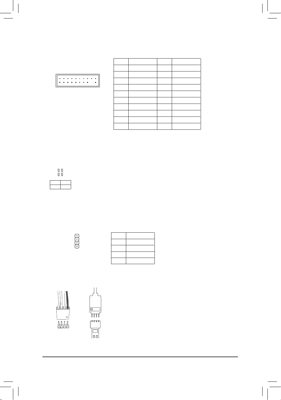
17) TPM (Trusted Platform Module Header)
YoumayconnectaTPM(TrustedPlatformModule)tothisheader.
Pin No. Denition Pin No. Denition
1 LCLK 11 LAD0
2GND 12 GND
3LFRAME 13 NC
4 No Pin 14 NC
5LRESET 15 SB3V
6 NC 16 SERIRQ
7LAD3 17 GND
8LAD2 18 NC
9 VCC3 19 NC
10 LAD1 20 NC
20
19
2
1
F_USB30 F_U
B_
F_ F_
_
B
BS_
B
SB_
B
_S
S_
_
B
_U
_
B
S
123
123
123
123
1
1
1
1
BSS
S
_S
SSU
1 2 3
S3 BSSS
U
__ 3
F_USB3F
S _
S _
S _
SF
B_
B_
F
_0
S
S
_0F
_F
_
_
__B
U
S _S
_
USB0_B
B_ F_USB3
Pin No. Denition
1 12V
2 G
3R
4 B
1
19) LED_C1 (CPU Cooler LED Strip/RGB LED Strip Extension Cable Header)
TheheadercanbeusedtoconnectaCPUcoolerLEDstriporastandard5050RGBLEDstrip(12V/G/R/B),
withmaximumpowerratingof2A(12V)andmaximumlengthof2m.
ConnectingtheCPUcoolerLEDstrip:
ConnecttheconnectoroftheCPUcoolerLEDstrip(markedwithanarrow)toPin1(12V)ofthisheader.
12V
1
+12V
Black wire
12V of the
LEDstrip
ConnectingthestandardLEDstrip:
ConnectoneendoftheRGB(RGBW)LEDstripextensioncabletothe
headerandtheotherendtoyourRGB(RGBW)LEDstrip.Theblack
wire(markedwithatriangleontheplug)oftheextensioncablemustbe
connectedtoPin1(12V)ofthisheader.The12Vpin(markedwithan
arrow)ontheotherendoftheextensioncablemustbelinedupwiththe
12VoftheLEDstrip.Becarefulwiththeconnectionorientationofthe
LEDstrip;incorrectconnectionmayleadtothedamageoftheLEDstrip.
— 19 —
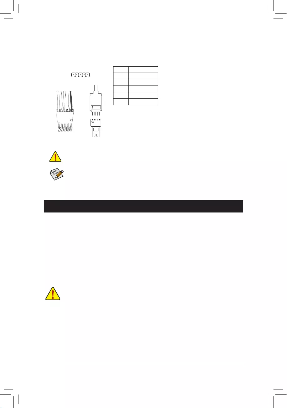
Pin No. Denition
1 12V
2 G
3R
4 B
5W
F_USB30 F_U
B_
F_ F_
_
B
BS_
B
SB_
B
_S
S_
_
B
_U
_
B
S
123
123
123
123
1
1
1
1
BSS
S
_S
SSU
1 2 3
S3 BSSS
U
__ 3
F_USB3F
S _
S _
S _
SF
B_
B_
F
_0
S
S
_0F
_F
_
_
__B
U
S _S
_
USB0_B
B_ F_USB3
1
Before installing the devices, be sure to turn off the devices and your computer. Unplug the power
cord from the power outlet to prevent damage to the devices.
20) LED_C2 (RGB (RGBW) LED Strip Extension Cable Header)
Theheadercanbeusedtoconnectastandard5050RGB(RGBW)LEDstrip(12V/G/R/B/W),withmaximum
powerratingof2A(12V)andmaximumlengthof2m.
ConnectoneendoftheRGB(RGBW)LEDstripextensioncabletothe
headerandtheotherendtoyourRGB(RGBW)LEDstrip.Theblack
wire(markedwithatriangleontheplug)oftheextensioncablemustbe
connectedtoPin1(12V)ofthisheader.The12Vpin(markedwithan
arrow)ontheotherendoftheextensioncablemustbelinedupwiththe
12VoftheLEDstrip.Becarefulwiththeconnectionorientationofthe
LEDstrip;incorrectconnectionmayleadtothedamageoftheLEDstrip.
12V
1
Black wire
12V of the
LEDstrip
Forhow to turn on/offthelights of theRGB (RGBW) LEDstrip, refer tothe instructions onin
Chapter2,»BIOSSetup.»
Chapter 2 BIOS Setup
BIOS(Basic Input and Output System) records hardware parameters of the system in theCMOS on the
motherboard.ItsmajorfunctionsincludeconductingthePower-OnSelf-Test(POST)duringsystemstartup,
saving system parameters and loading operating system, etc. BIOS includes a BIOS Setup program that allows
theusertomodifybasicsystemcongurationsettingsortoactivatecertainsystemfeatures.
Whenthepoweristurnedoff,thebatteryonthemotherboardsuppliesthenecessarypowertotheCMOSto
keepthecongurationvaluesintheCMOS.
ToaccesstheBIOSSetupprogram,pressthe<Delete>keyduringthePOSTwhenthepoweristurnedon.
ToupgradetheBIOS,useeithertheGIGABYTEQ-Flashor@BIOSutility.
•Q-Flash allows the user to quickly and easily upgrade or back up BIOS without entering the operating system.
•@BIOSisaWindows-basedutilitythatsearchesanddownloadsthelatestversionofBIOSfromtheInternet
and updates the BIOS.
•BecauseBIOSashingispotentiallyrisky,ifyoudonotencounterproblemsusingthecurrentversionofBIOS,
itisrecommendedthatyounotashtheBIOS.ToashtheBIOS,doitwithcaution.InadequateBIOSashing
may result in system malfunction.
•Itisrecommendedthatyounotalterthedefaultsettings(unlessyouneedto)topreventsysteminstabilityorother
unexpected results. Inadequately altering the settings may result in system’s failure to boot. If this occurs, try to
cleartheCMOSvaluesandresettheboardtodefaultvalues.(Refertothe»LoadOptimizedDefaults»sectionin
thischapterorintroductionsofthebattery/clearCMOSjumperinChapter1forhowtocleartheCMOSvalues.)
— 20 —
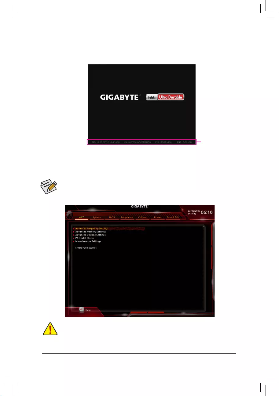
2-1 Startup Screen
The following startup Logo screen will appear when the computer boots.
(SampleBIOSVersion:T1c)
Function Keys
•Whenthesystemisnotstableasusual,selecttheLoad Optimized Defaults item to set your system to its defaults.
•The BIOS Setup menus described in this chapter are for reference only and may differ by BIOS version.
TherearetwodifferentBIOSmodesasfollowsandyoucanusethe<F2>keytoswitchbetweenthetwomodes.
The Classic Setup mode provides detailed BIOS settings. You can press the arrow keys on your keyboard to move
amongtheitemsandpress<Enter>toacceptorenterasub-menu.Oryoucanuseyourmousetoselecttheitemyou
want. Easy Mode allows users to quickly view their current system information or to make adjustments for optimum
performance.InEasyMode,youcanuseyourmousetomovethroughcongurationitems.
2-2 M.I.T.
Whetherthesystemwillworkstablywiththeoverclock/overvoltagesettingsyoumadeisdependentonyouroverall
systemcongurations.Incorrectlydoingoverclock/overvoltagemayresultindamagetoCPU,chipset,ormemory
and reduce the useful life of these components. This page is for advanced users only and we recommend you not to
alterthedefaultsettingstopreventsysteminstabilityorotherunexpectedresults.(Inadequatelyalteringthesettings
mayresultinsystem’sfailuretoboot.Ifthisoccurs,cleartheCMOSvaluesandresettheboardtodefaultvalues.)
— 21 —

(Note) ThisitemispresentonlywhenyouinstallaCPUthatsupportsthisfeature.
`Advanced Frequency Settings
&Host Clock Value
DisplaysthecurrentoperatingHostClockfrequency.
&CPU Clock Ratio
Allows you to alter the clock ratio for the installed CPU. The adjustable range is dependent on the CPU
being installed.
&CPU Frequency
DisplaysthecurrentoperatingCPUfrequency.
`Advanced CPU Core Settings
&CPU Clock Ratio, CPU Frequency
The settings above are synchronous to those under the same items on the Advanced Frequency Settings
menu.
&Core Performance Boost Ratio (Note)
Allows you alter the ratio for the CPB. The adjustable range is dependent on the CPU being installed.
(Default:Auto)
&Core Performance Boost (Note)
Allowsyou to determine whether to enable theCore Performance Boost (CPB) technology,a CPU
performance-boosttechnology.(Default:Auto)
&Turbo Performance Boost Ratio (Note)
AllowsyoutodeterminewhethertoimproveCPUperformance.(Default:Disabled)
&AMD Cool&Quiet function
Enabled LetstheAMDCool’n’QuietdriverdynamicallyadjusttheCPUclockandVIDtoreduce
heatoutputfromyourcomputeranditspowerconsumption.(Default)
Disabled Disablesthisfunction.
&SVM Mode
VirtualizationenhancedbyVirtualizationTechnologywillallowaplatformtorunmultipleoperatingsystems
andapplicationsinindependentpartitions.Withvirtualization,onecomputersystemcanfunctionasmultiple
virtualsystems.(Default:Enabled)
&C6 Mode
(Note)
AllowsyoutodeterminewhethertolettheCPUenterC6modeinsystemhaltstate.Whenenabled,the
CPU core frequency will be reduced during system halt state to decrease power consumption. The C6
stateisamoreenhancedpower-savingstatethanC1.(Default:Enabled)
&Global C-state Control
(Note)
AllowsyoutodeterminewhethertolettheCPUenterCstates.Whenenabled,theCPUcorefrequency
willbereducedduringsystemhaltstatetodecreasepowerconsumption.(Default:Enabled)
&SMT Mode
(Note)
Allows you to enable or disable the CPU Simultaneous Multi-Threading technology. This feature only works
for operating systems that support multi-processor mode. AutoletstheBIOSautomaticallycongurethis
setting.(Default:Auto)
&Downcore Control
(Note)
AllowsyoutoselectthenumberofCPUcorestoenable(thenumberofCPUcoresmayvarybyCPU).
AutoletstheBIOSautomaticallycongurethissetting.(Default:Auto)
— 22 —

&ExtremeMemoryProle(X.M.P.)(Note)
AllowstheBIOStoreadtheSPDdataonXMPmemorymodule(s)toenhancememoryperformancewhen
enabled.
Disabled Disablesthisfunction.(Default)
Prole1 UsesProle1settings.
Prole2(Note) UsesProle2settings.
&System Memory Multiplier
Allows you to set the system memory multiplier. AutosetsmemorymultiplieraccordingtomemorySPD
data.(Default:Auto)
&Memory Frequency (MHz)
Therstmemoryfrequencyvalueisthenormaloperatingfrequencyofthememorybeingused;thesecond
is the memory frequency that is automatically adjusted according to the System Memory Multiplier settings.
`Advanced Memory Settings
&
ExtremeMemoryProle(X.M.P.) (Note)
,
System Memory Multiplier,
Memory Frequency(Mhz)
The settings above are synchronous to those under the same items on the Advanced Frequency Settings
menu.
&Memory Timing Mode
Manual and Advanced Manual allows the Channel Interleaving, Rank Interleaving, and memory timing
settingsbelowtobecongurable.Optionsare:Auto(default),Manual,AdvancedManual.
&ProleDDRVoltage
Whenusinganon-XMPmemorymoduleorExtremeMemoryProle(X.M.P.) is set to Disabled, the value
isdisplayedaccordingtoyourmemoryspecication.WhenExtremeMemoryProle(X.M.P.) is set to
Prole1 or Prole2,thevalueisdisplayedaccordingtotheSPDdataontheXMPmemory.
&Channel Interleaving
Enables or disables memory channel interleaving. Enabled allows the system to simultaneously access
differentchannelsofthememorytoincreasememoryperformanceandstability.(Default:Auto)
&Rank Interleaving
Enables or disables memory rank interleaving. Enabled allows the system to simultaneously access different
ranksofthememorytoincreasememoryperformanceandstability.(Default:Auto)
`Channel A/B Memory Sub Timings
This sub-menu provides memory timing settings for each channel of memory. The respective timing setting
screensarecongurableonlywhenMemory Timing Mode is set to Manual or Advanced Manual. Note: Your
system may become unstable or fail to boot after you make changes on the memory timings. If this occurs,
pleaseresettheboardtodefaultvaluesbyloadingoptimizeddefaultsorclearingtheCMOSvalues.
`Advanced Voltage Settings
This sub-menu allows you to set CPU, chipset and memory voltages.
`PC Health Status
&Reset Case Open Status
Disabled Keepsorclearstherecordofpreviouschassisintrusionstatus.(Default)
Enabled Clears the record of previous chassis intrusion status and the Case Openeldwill
show»No»atnextboot.
(Note) ThisitemispresentonlywhenyouinstallaCPUandamemorymodulethatsupportthisfeature.
— 23 —

&Case Open
DisplaysthedetectionstatusofthechassisintrusiondetectiondeviceattachedtothemotherboardCI
header.Ifthesystemchassiscoverisremoved,thiseldwillshow«Yes»,otherwiseitwillshow«No».To
clear the chassis intrusion status record, set Reset Case Open Status to Enabled, save the settings to
the CMOS, and then restart your system.
& CPU Vcore/CPU VDDP/DRAM Channel A/B Voltage/+3.3V/+5V/+12V/VCORE SOC
Displaysthecurrentsystemvoltages.
`Miscellaneous Settings
&PCIeSlotConguration
Allows you to set the operation mode of the PCI Express slots to Gen 1, Gen 2, or Gen 3. Actual operation
modeissubjecttothehardwarespecicationofeachslot.AutoletstheBIOSautomaticallycongurethis
setting.(Default:Auto)
&3DMark01 Enhancement
Allowsyoutodeterminewhethertoenhancesomelegacybenchmarkperformance.(Default:Disabled)
`Smart Fan 5 Settings
&Monitor
Allowsyoutoselectatargettomonitorandtomakefurtheradjustment.(Default:CPUFAN)
&Fan Speed Control
Allows you to determine whether to enable the fan speed control function and adjust the fan speed.
Normal Allows the fan to run at different speeds according to the temperature. You can adjust
the fan speed with System Information Viewer based on your system requirements.
(Default)
Silent Allows the fan to run at slow speeds.
Manual Allows you to control the fan speed in the curve graph.
Full Speed Allows the fan to run at full speeds.
&Fan Control Use Temperature Input
Allows you to select the reference temperature for fan speed control.
&Temperature Interval
Allows you to select the temperature interval for fan speed change.
&Fan/Pump Control Mode
Auto Lets the BIOS automatically detect the type of fan/pump installed and sets the optimal
controlmode.(Default)
Voltage Voltage mode is recommended for a 3-pin fan/pump.
PWM PWMmodeisrecommendedfora4-pinfan/pump.
&Temperature
Displaysthecurrenttemperatureoftheselectedtargetarea.
&Fan Speed
Displayscurrentfan/pumpspeeds.
&Temperature Warning Control
Setsthewarningthresholdfortemperature.When temperature exceeds the threshold, BIOSwillemit
warningsound.Optionsare:Disabled(default),60oC/140oF, 70oC/158oF, 80oC/176oF, 90oC/194oF.
&Fan/Pump Fail Warning
Allows the system to emit warning sound if the fan/pump is not connected or fails. Check the fan/pump
conditionorfan/pumpconnectionwhenthisoccurs.(Default:Disabled)
— 24 —
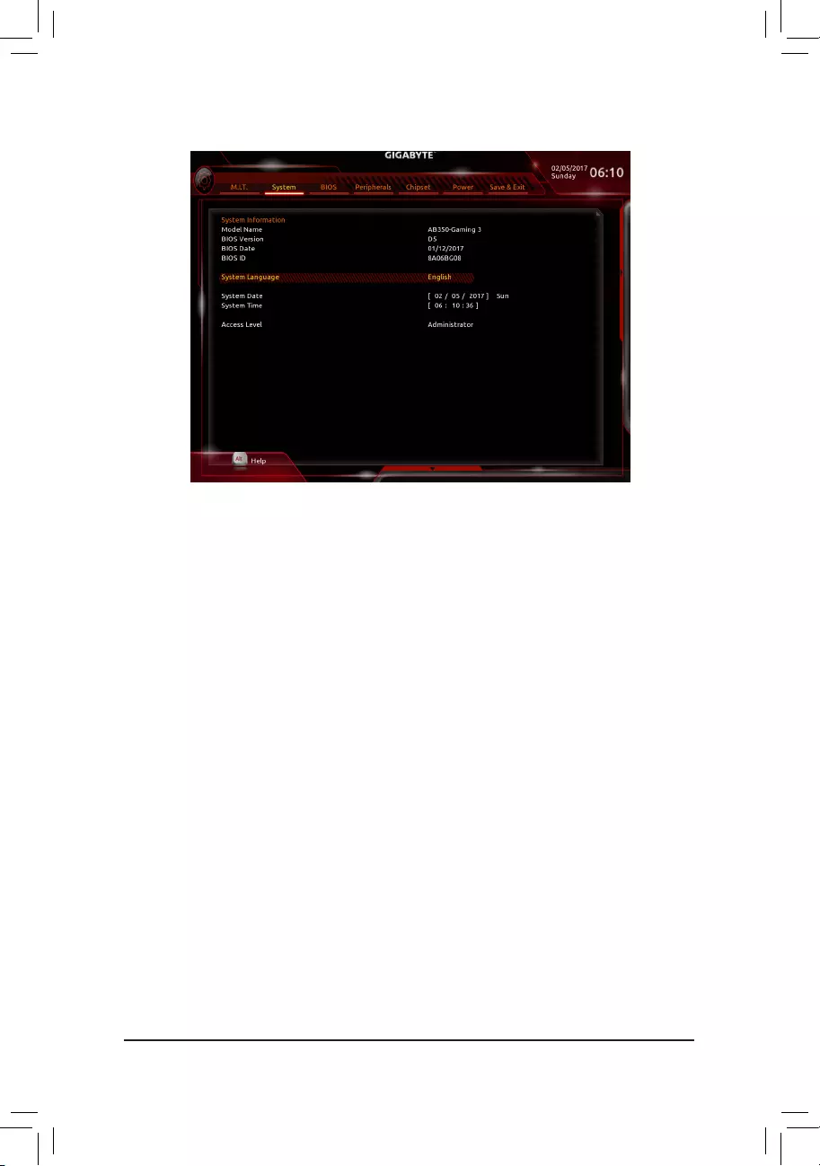
2-3 System
This section provides information on your motherboard model and BIOS version. You can also select the default
language used by the BIOS and manually set the system time.
&System Language
Selects the default language used by the BIOS.
&System Date
Setsthesystemdate.Thedateformatisweek(read-only),month,date,andyear.Use<Enter>toswitch
betweentheMonth,Date,andYeareldsandusethe<PageUp>or<PageDown>keytosetthedesired
value.
&System Time
Sets the system time. The time format is hour, minute, and second. For example, 1 p.m. is 13:00:00. Use
<Enter>toswitchbetweentheHour,Minute,andSecondeldsandusethe<PageUp>or<PageDown>
key to set the desired value.
&Access Level
Displaysthecurrentaccessleveldependingonthetypeofpasswordprotectionused.(Ifnopasswordis
set, the default will display as Administrator.)TheAdministratorlevelallowsyoutomakechangestoall
BIOS settings; the User level only allows you to make changes to certain BIOS settings but not all.
— 25 —
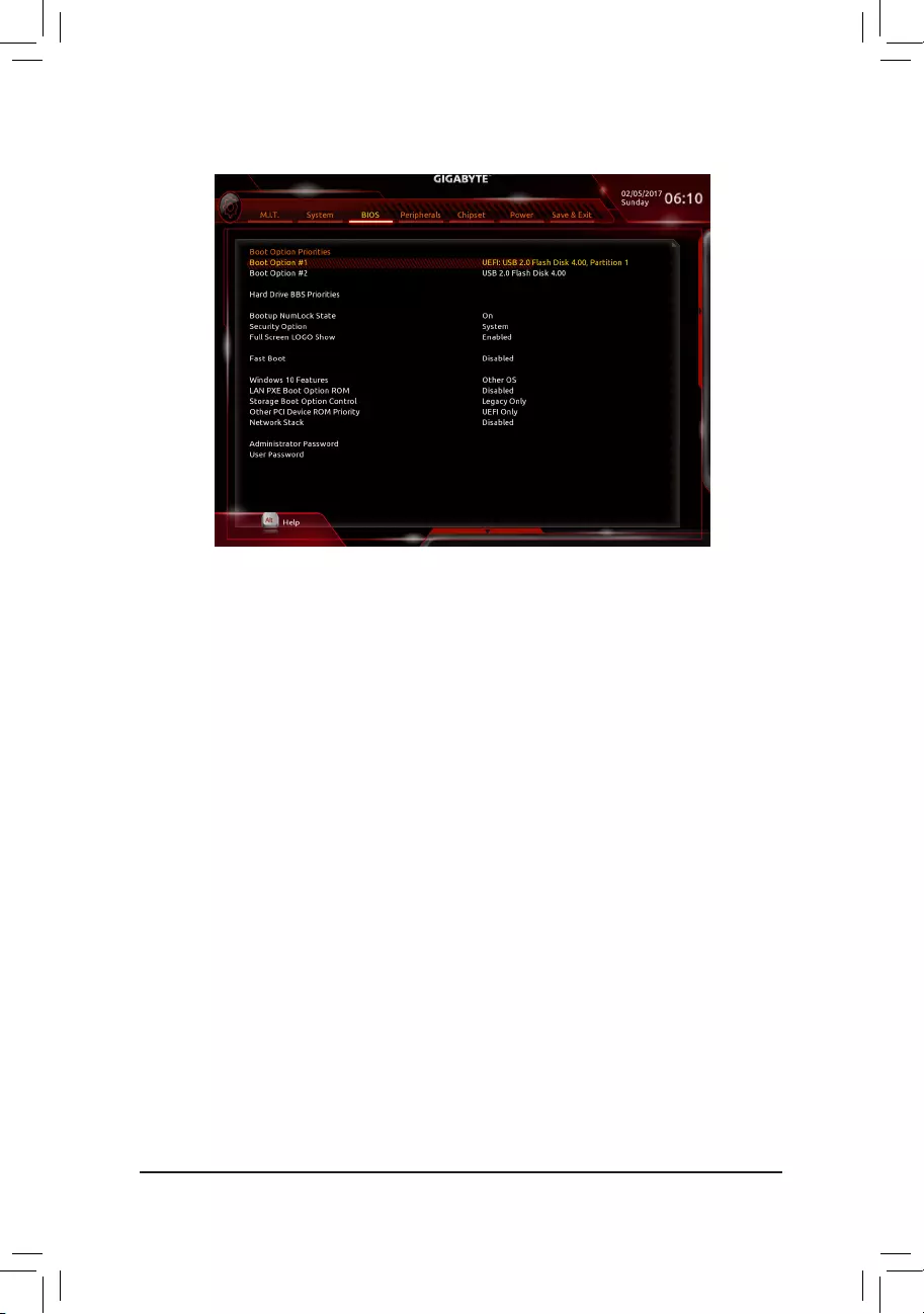
&Boot Option Priorities
Speciestheoverallbootorderfromtheavailabledevices.RemovablestoragedevicesthatsupportGPT
formatwillbeprexedwith«UEFI:»stringonthebootdevicelist.Tobootfromanoperatingsystemthat
supportsGPTpartitioning,selectthedeviceprexedwith»UEFI:»string.
OrifyouwanttoinstallanoperatingsystemthatsupportsGPTpartitioningsuchasWindows764-bit,select
theopticaldrivethatcontainstheWindows764-bitinstallationdiskandisprexedwith»UEFI:»string.
&Hard Drive/CD/DVD ROM Drive/Floppy Drive/Network Device BBS Priorities
Speciesthebootorderforaspecicdevicetype,suchasharddrives,opticaldrives,oppydiskdrives,
anddevicesthatsupportBootfromLANfunction,etc.Press<Enter>onthisitemtoenterthesubmenuthat
presents the devices of the same type that are connected. This item is present only if at least one device
for this type is installed.
&Bootup NumLock State
EnablesordisablesNumlockfeatureonthenumerickeypadofthekeyboardafterthePOST.(Default:On)
&Security Option
Specieswhetherapasswordisrequiredeverytimethesystemboots,oronlywhenyouenterBIOSSetup.
Afterconguringthisitem,setthepassword(s)undertheAdministrator Password/User Password item.
Setup A password is only required for entering the BIOS Setup program.
System A password is required for booting the system and for entering the BIOS Setup program.
(Default)
&Full Screen LOGO Show
Allows you to determine whether to display the GIGABYTE Logo at system startup. Disabled skips the
GIGABYTELogowhenthesystemstartsup.(Default:Enabled)
&Fast Boot
Enables or disables Fast Boot to shorten the OS boot process. Ultra Fast provides the fastest bootup
speed.(Default:Disabled)
2-4 BIOS
— 26 —

&SATA Support
AllSataDevices AllSATAdevicesarefunctionalintheoperatingsystemandduringthePOST.
(Default)
LastBootHDDOnly Exceptforthepreviousbootdrive,allSATAdevicesaredisabledbeforetheOS
boot process completes.
ThisitemiscongurableonlywhenFast Boot is set to Enabled or Ultra Fast.
&VGA Support
Allows you to select which type of operating system to boot.
Auto EnableslegacyoptionROMonly.
EFIDriver EnablesEFIoptionROM.(Default)
ThisitemiscongurableonlywhenFast Boot is set to Enabled or Ultra Fast.
&USB Support
Disabled AllUSBdevicesaredisabledbeforetheOSbootprocesscompletes.
Full Initial All USB devices are functional in the operating system and during the POST.
(Default)
Partial Initial Part of the USB devices are disabled before the OS boot process completes.
ThisitemiscongurableonlywhenFast Boot is set to Enabled. This function is disabled when Fast Boot
is set to Ultra Fast.
&PS2 Devices Support
Disabled AllPS/2devicesaredisabledbeforetheOSbootprocesscompletes.
Enabled All PS/2 devices are functional in the operating system and during the POST.
(Default)
ThisitemiscongurableonlywhenFast Boot is set to Enabled. This function is disabled when Fast Boot
is set to Ultra Fast.
&NetWork Stack Driver Support
Disabled Disablesbootingfromthenetwork.(Default)
Enabled Enables booting from the network.
ThisitemiscongurableonlywhenFast Boot is set to Enabled or Ultra Fast.
&Windows 10 Features
Allowsyoutoselecttheoperatingsystemtobeinstalled.(Default:OtherOS)
&CSM Support
EnablesordisablesUEFICSM(CompatibilitySupportModule)tosupportalegacyPCbootprocess.
Enabled EnablesUEFICSM.(Default)
Disabled DisablesUEFICSMandsupportsUEFIBIOSbootprocessonly.
ThisitemiscongurableonlywhenWindows 10 Features is set to Windows 10 or Windows 10 WHQL.
&LAN PXE Boot Option ROM
AllowsyoutoselectwhethertoenablethelegacyoptionROMfortheLANcontroller.(Default:Disabled)
ThisitemiscongurableonlywhenCSM Support is set to Enabled.
&Storage Boot Option Control
AllowsyoutoselectwhethertoenabletheUEFIorlegacyoptionROMforthestoragedevicecontroller.
Disabled DisablesoptionROM.
UEFIOnly EnablesUEFIoptionROMonly.
LegacyOnly EnableslegacyoptionROMonly.(Default)
ThisitemiscongurableonlywhenCSM Support is set to Enabled.
— 27 —

&Other PCI Device ROM Priority
AllowsyoutoselectwhethertoenabletheUEFIorLegacyoptionROMforthePCIdevicecontrollerother
than the LAN, storage device, and graphics controllers.
Disabled DisablesoptionROM.
UEFIOnly EnablesUEFIoptionROMonly.(Default)
LegacyOnly EnableslegacyoptionROMonly.
ThisitemiscongurableonlywhenCSM Support is set to Enabled.
&Network Stack
DisablesorenablesbootingfromthenetworktoinstallaGPTformatOS,suchasinstallingtheOSfrom
theWindowsDeploymentServicesserver.(Default:Disabled)
&Ipv4 PXE Support
EnablesordisablesIPv4PXESupport.ThisitemiscongurableonlywhenNetwork Stack is enabled.
&Ipv4 HTTP Support
EnablesordisablesHTTPbootsupportforIPv4.ThisitemiscongurableonlywhenNetwork Stack is
enabled.
&Ipv6 PXE Support
EnablesordisablesIPv6PXESupport.ThisitemiscongurableonlywhenNetwork Stack is enabled.
&Ipv6 HTTP Support
EnablesordisablesHTTPbootsupportforIPv6.ThisitemiscongurableonlywhenNetwork Stack is
enabled.
&Administrator Password
Allowsyoutocongureanadministratorpassword.Press<Enter>onthisitem,typethepassword,and
thenpress<Enter>.Youwillberequestedtoconrmthepassword.Typethepasswordagainandpress
<Enter>.Youmustentertheadministratorpassword(oruserpassword)atsystemstartupandwhenentering
BIOSSetup.Differingfromtheuserpassword,theadministratorpasswordallowsyoutomakechangesto
all BIOS settings.
&User Password
Allowsyoutocongureauserpassword.Press<Enter>onthisitem,typethepassword,andthenpress
<Enter>.Youwillberequestedtoconrmthepassword.Typethepasswordagainandpress<Enter>.
Youmustentertheadministratorpassword(oruserpassword)atsystemstartupandwhenenteringBIOS
Setup. However, the user password only allows you to make changes to certain BIOS settings but not all.
Tocancelthepassword,press<Enter>onthepassworditemandwhenrequestedforthepassword,enter
thecorrectonerst.Whenpromptedforanewpassword,press<Enter>withoutenteringanypassword.
Press<Enter>againwhenpromptedtoconrm.
NOTE:BeforesettingtheUserPassword,besuretosettheAdministratorPasswordrst.
— 28 —
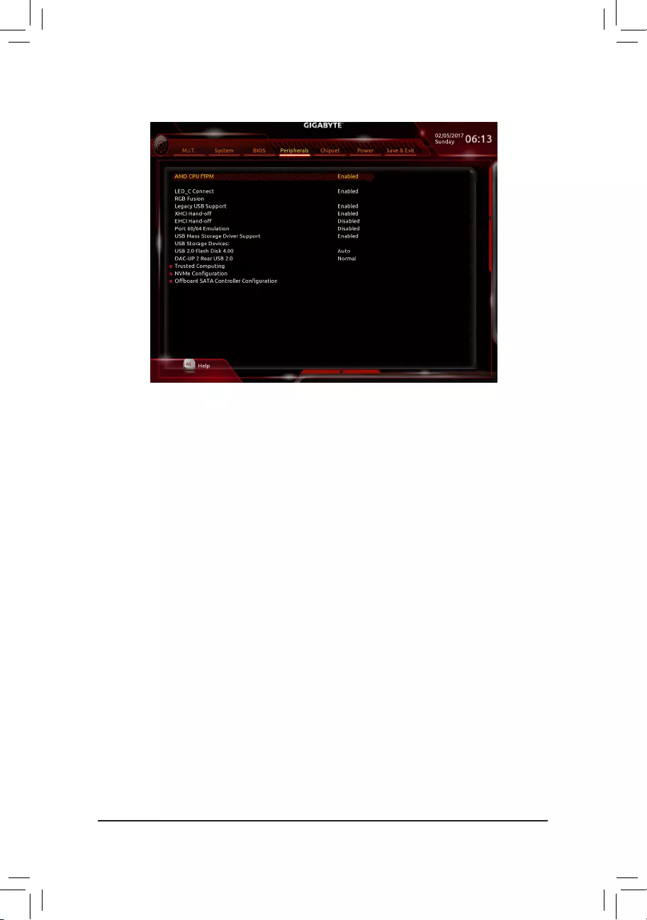
2-5 Peripherals
&AMD CPU fTPM
EnablesordisablestheTPM2.0functionintegratedintheAMDCPU.(Default:Enabled)
&LED_C Connect
EnablesordisablesthelightsoftheRGB(RGBW)LEDstripconnectedtotheLED_C2headeronthe
motherboard.(Default:Enabled)
&RGB Fusion
AllowsyoutosettheLEDlightingmodeforthemotherboard.
Off Disablesthisfunction.
PulseMode AllLEDssimultaneouslyfadeinandfadeout.
ColorCycle AllLEDssimultaneouslycyclethroughafullspectrumofcolors.
StaticMode AllLEDsemitasinglecolor.(Default)
FlashMode AllLEDssimultaneouslyashonandoff.
&Legacy USB Support
AllowsUSBkeyboard/mousetobeusedinMS-DOS.(Default:Enabled)
&XHCI Hand-off
Determineswhether toenable XHCIHand-offfeature foran operatingsystem withoutXHCI Hand-off
support.(Default:Enabled)
&EHCI Hand-off
Determineswhether toenable EHCIHand-offfeature foran operatingsystem withoutEHCI Hand-off
support.(Default:Disabled)
&Port 60/64 Emulation
Enables or disables emulation of I/O ports 64h and 60h. This should be enabled for full legacy support
forUSBkeyboards/miceinMS-DOSorinoperatingsystemthatdoesnotnativelysupportUSBdevices.
(Default:Disabled)
&USB Mass Storage Driver Support
EnablesordisablessupportforUSBstoragedevices.(Default:Enabled)
— 29 —

&USB Storage Devices
DisplaysalistofconnectedUSBmassstoragedevices.ThisitemappearsonlywhenaUSBstoragedevice
is installed.
&DAC-UP 2 Rear USB 2.0 (Output Voltage of USB 2.0 Port on the Back Panel)
Allows you to increase the output voltage of the USB 2.0 port on the back panel to strengthen the stability
ofyourUSBdevice(s).
Normal Keepstheoriginaloutputvoltage.(Default)
DisableUSBbuspower DisablesthepoweroftheUSBconnectors.High-endaudioplayersmay
connect their own external USB power source.
Voltage Compensation +0.1V Adds 0.1V to the original output voltage.
Voltage Compensation +0.2V Adds 0.2V to the original output voltage.
Voltage Compensation +0.3V Adds 0.3V to the original output voltage.
`Trusted Computing
EnablesordisablesTrustedPlatformModule(TPM).
`NVMeConguration
DisplaysinformationonyourM.2NVMEPCIeSSDifinstalled.
`OffBoardSATAControllerConguration
DisplaysinformationonyourM.2PCIeSSDifinstalled.
— 30 —
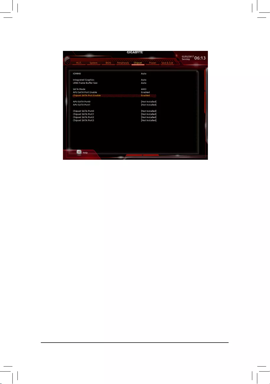
&IOMMU
EnablesordisablesAMDIOMMUsupport.(Default:Auto)
&Integrated Graphics (Note)
Enables or disables the onboard graphics function.
Auto The BIOS will automatically enable or disable the onboard graphics depending on the
graphicscardbeinginstalled.(Default)
Disabled Disablestheonboardgraphics.
&UMA Frame Buffer Size (Note)
Framebuffersizeisthetotalamountofsystemmemoryallocatedsolelyfortheonboardgraphicscontroller.
MS-DOS,forexample,willuseonlythismemoryfordisplay.Optionsare:Auto(default),32M,64M,128M,
256M, 512M, 1G, 2G.
&SATA Mode
EnablesordisablesRAIDfortheSATAcontrollersorcongurestheSATAcontrollerstoAHCImode.
RAID EnablesRAIDfortheSATAcontroller.
AHCI CongurestheSATAcontrollerstoAHCImode.AdvancedHostControllerInterface
(AHCI)isaninterfacespecicationthatallowsthestoragedrivertoenableadvanced
SerialATAfeaturessuchasNativeCommandQueuingandhotplug.(Default)
&APU SATA Port Enable (ASATA3 0,1 Connectors)
EnablesordisablestheintegratedSATAcontrollers.(Default:Enabled)
&Chipset SATA Port Enable (SATA3 0,1,2,3 Connectors)
EnablesordisablestheintegratedSATAcontrollers.(Default:Enabled)
&APU SATA Port 0/1
Enables or disables each SATA port.
&Chipset SATA Port 0/1/2/3
Enables or disables each SATA port.
2-6 Chipset
(Note) ThisitemispresentonlywhenyouinstallaCPUthatsupportsthisfeature.
— 31 —
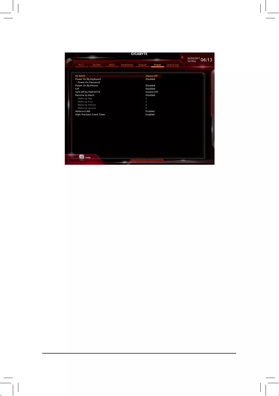
&AC BACK
DeterminesthestateofthesystemafterthereturnofpowerfromanACpowerloss.
Memory The system returns to its last known awake state upon the return of the AC power.
Always On The system is turned on upon the return of the AC power.
AlwaysOff ThesystemstaysoffuponthereturnoftheACpower.(Default)
&Power On By Keyboard
Allows the system to be turned on by a PS/2 keyboard wake-up event.
Note: To use this function, you need an ATX power supply providing at least 1A on the +5VSB lead.
Disabled Disablesthisfunction.(Default)
Password Set a password with 1~5 characters to turn on the system.
Keyboard98 PressPOWERbuttonontheWindows98keyboardtoturnonthesystem.
Any key Press any key to turn on the system.
&Power On Password
Set the password when Power On By Keyboard is set to Password.
Press<Enter>onthisitemandsetapasswordwithupto5charactersandthenpress<Enter>toaccept.
Toturnonthesystem,enterthepasswordandpress<Enter>.
Note:Tocancelthepassword,press<Enter>onthisitem.Whenpromptedforthepassword,press<Enter>
again without entering the password to clear the password settings.
&Power On By Mouse
Allows the system to be turned on by a PS/2 mouse wake-up event.
Note: To use this function, you need an ATX power supply providing at least 1A on the +5VSB lead.
Disabled Disablesthisfunction.(Default)
Move Move the mouse to turn on the system.
DoubleClick Doubleclickonleftbuttononthemousetoturnonthesystem.
&ErP
DetermineswhethertoletthesystemconsumeleastpowerinS5(shutdown)state.Note:Whenthisitem
is set to Enabled,thefollowingfunctionswillbecomeunavailable:ResumebyAlarm,PMEeventwake
up, power on by mouse, power on by keyboard, and wake on LAN.
2-7 Power
— 32 —

&Soft-Off by PWR-BTTN
ConguresthewaytoturnoffthecomputerinMS-DOSmodeusingthepowerbutton.
Instant-Off Pressthepowerbuttonandthenthesystemwillbeturnedoffinstantly.(Default)
Delay4Sec. Pressandholdthepowerbuttonfor4secondstoturnoffthesystem.Ifthepower
button is pressed for less than 4 seconds, the system will enter suspend mode.
&Resume by Alarm
Determineswhethertopoweronthesystematadesiredtime.(Default:Disabled)
If enabled, set the date and time as following:
Wakeupday:Turnonthesystemataspecictimeoneachdayoronaspecicdayinamonth.
Wakeuphour/minute/second:Setthetimeatwhichthesystemwillbepoweredonautomatically.
Note:Whenusingthisfunction,avoidinadequateshutdownfromtheoperatingsystemorremovalofthe
AC power, or the settings may not be effective.
&Wake on LAN
EnablesordisablesthewakeonLANfunction.(Default:Enabled)
&High Precision Event Timer
EnablesordisablesHighPrecisionEventTimer(HPET)intheoperatingsystem.(Default:Enabled)
— 33 —

2-8 Save & Exit
&Save & Exit Setup
Press<Enter>onthisitemandselectYes. This saves the changes to the CMOS and exits the BIOS Setup
program. Select Noorpress<Esc>toreturntotheBIOSSetupMainMenu.
&Exit Without Saving
Press<Enter>onthisitemandselectYes. This exits the BIOS Setup without saving the changes made
in BIOS Setup to the CMOS. Select Noorpress<Esc>toreturntotheBIOSSetupMainMenu.
&Load Optimized Defaults
Press<Enter>onthisitemandselectYes to load the optimal BIOS default settings. The BIOS defaults
settingshelpthesystemtooperateinoptimumstate.AlwaysloadtheOptimizeddefaultsafterupdating
the BIOS or after clearing the CMOS values.
&Boot Override
Allowsyoutoselectadevicetobootimmediately.Press<Enter>onthedeviceyouselectandselectYes
toconrm.Yoursystemwillrestartautomaticallyandbootfromthatdevice.
&SaveProles
ThisfunctionallowsyoutosavethecurrentBIOSsettingstoaprole.Youcancreateupto8prolesand
saveasSetupProle1~SetupProle8.Press<Enter>tocomplete.OryoucanselectSelect File in
HDD/FDD/USBtosavetheproletoyourstoragedevice.
&LoadProles
If your system becomes unstable and you have loaded the BIOS default settings, you can use this function
toloadtheBIOSsettingsfromaprolecreatedbefore,withoutthehasslesofreconguringtheBIOS
settings.Firstselecttheproleyouwishtoloadandthenpress<Enter>tocomplete.YoucanselectSelect
File in HDD/FDD/USBtoinputtheprolepreviouslycreatedfromyourstoragedeviceorloadtheprole
automatically created by the BIOS, such as reverting the BIOS settings to the last settings that worked
properly(lastknowngoodrecord).
— 34 —
Chapter 3 Appendix
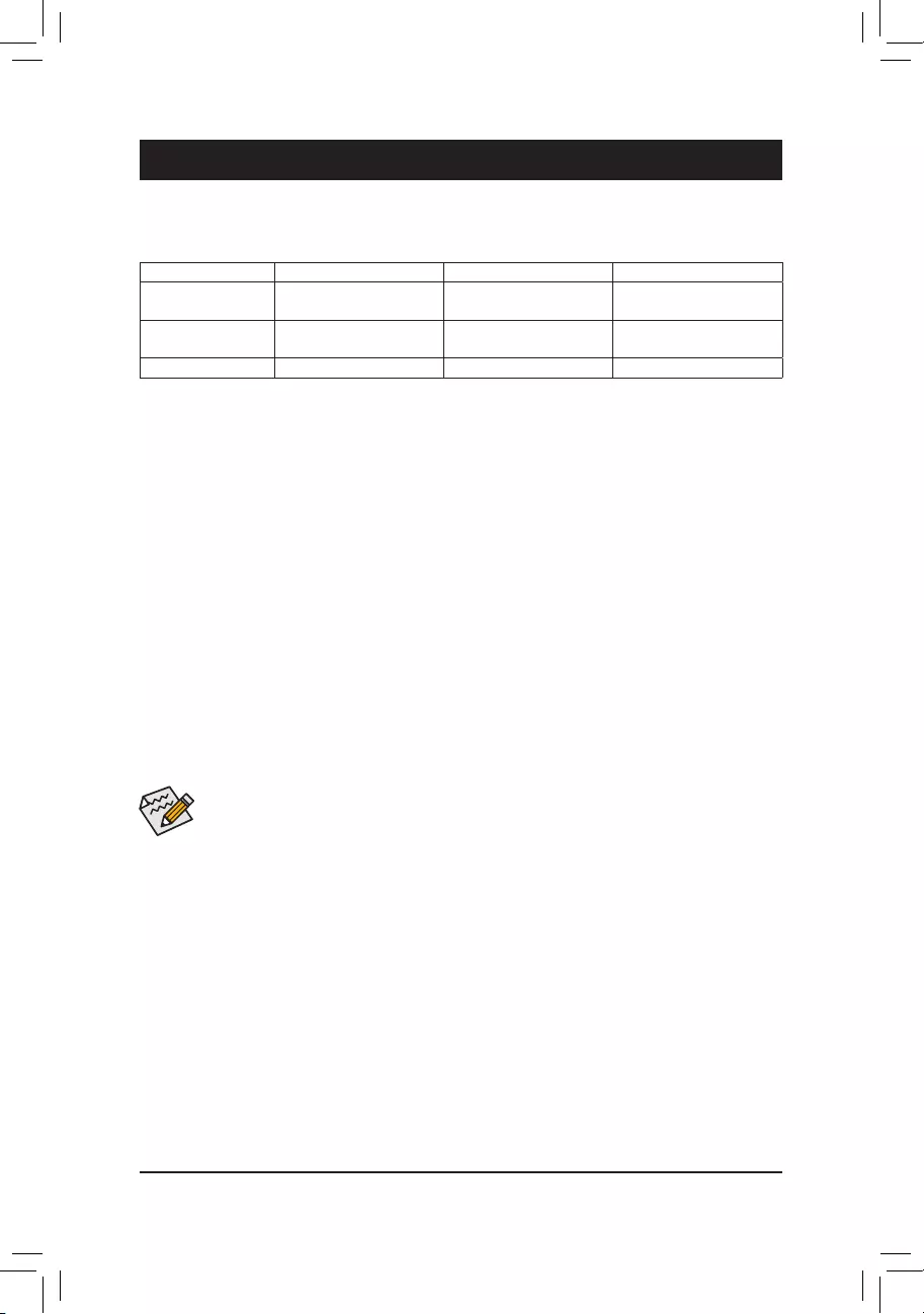
3-1 ConguringaRAIDSet
RAID Levels
RAID 0 RAID 1 RAID 10
Minimum Number of
HardDrives ≥2 2 4
Array Capacity Number of hard drives *
Sizeofthesmallestdrive
Sizeofthesmallestdrive (Numberofharddrives/2)*
Sizeofthesmallestdrive
Fault Tolerance No Yes Yes
Before you begin, please prepare the following items:
•AtleasttwoSATAharddrivesorM.2SATASSDs(toensureoptimalperformance,itisrecommendedthat
youusetwoharddriveswithidenticalmodelandcapacity).(Note)
•AWindowssetupdisk.
•Motherboard driver disk.
•A USB thumb drive.
ConguringSATAControllers
A. Installing hard drives
Installtheharddrives/SSDsintheSATA/M.2connectorsonthemotherboard.Thenconnectthepowerconnectors
from your power supply to the hard drives.
B.ConguringSATAcontrollermodeinBIOSSetup
MakesuretoconguretheSATAcontrollermodecorrectlyinsystemBIOSSetup.
Steps:
1. Turnonyourcomputerandpress<Delete>toenterBIOSSetupduringthePOST(Power-OnSelf-Test).
Under Chipset, ensure APU SATA Port Enable and Chipset SATA Port Enable are enabled. Set SATA
Mode to RAID. Then save the settings and restart your computer.
2. IfyouwanttocongureUEFIRAID,followthestepsin«C-1.»ToenterthelegacyRAIDROM,savethe
settingsandexitBIOSSetup.Referto»C-2″formoreinformation.
The BIOS Setup menus described in this section may differ from the exact settings for your motherboard.
The actual BIOS Setup menu options you will see shall depend on the motherboard you have and
the BIOS version.
(Note) Referto»1-7InternalConnectors,»fortheinstallationnoticesfortheM.2andSATAconnectors.
C-1.UEFIRAIDConguration
OnlyWindows1064-bitsupportsUEFIRAIDconguration.
Step:
1. In BIOS Setup, go to BIOS and set Windows 10 Features to Windows 10 and CSM Support to Disabled.
Save the changes and exit BIOS Setup.
2. After the system reboot, enter BIOS Setup again. Then enter the Peripherals\RAIDXpert2Conguration
Utility sub-menu.
3. On the RAIDXpert2CongurationUtilityscreen,press<Enter>onArray Management to enter the Create
Arrayscreen.Then,selectaRAIDlevel.RAIDlevelssupportedincludeRAID0,RAID1,andRAID10(the
selectionsavailabledependonthenumberoftheharddrivesbeinginstalled).Next,press<Enter>onSelect
Physical Disks to enter the Select Physical Disks screen.
— 35 —

PleasevisitGIGABYTE’swebsitefordetailsonconguringaRAIDarray.
C-2.ConguringLegacyRAIDROM
EnterthelegacyRAIDBIOSsetuputilitytocongureaRAIDarray.Skipthisstepandproceedwiththeinstallation
ofWindowsoperatingsystemforanon-RAIDconguration.
Step:
1. After the POST memory test begins and before the operating system boot begins, look for a message which
says»Press<Ctrl-R>toCongure».Press<Ctrl>+<R>toentertheRAIDBIOSsetuputility.
2. Tocreateanewarray,press<Enter>ontheCreateArrayoption.
3. The selection bar will move to the Disks section on the right of the screen. Select the hard drives to be
includedintheRAIDarray.Usetheupordownarrowkeytoselectaharddriveandpress<Insert>.The
selectedharddrivewillbeshowningreen.Tousealloftheharddrives,simplypress<A>toselectall.Then
press<Enter>andtheselectionbarwillmovetotheUser Input section on the left bottom of the screen.
4. First,selectaRAIDmodeandpress<Enter>.Theselectionsavailabledependonthenumberoftheharddrives
beinginstalled.Thenfollowtheon-screeninstructionstospecifythearraysize.YoucanselectAll available
spacetousethemaximumsizeallowedorusetheupordownarrowkeytoadjustthesizeandpress<Enter>.
5. Selectacachingmode.OptionsincludeRead/Write,ReadOnly,andNone.Thenpress<Enter>toproceed.
6. Finally,amessagewhichsays«ConrmCreationofArray»willappear.Press<C>toconrmor<Esc>to
return to the previous screen.
7. Whencompleted,youwillseethenewarrayonthemainscreen.ToexittheRAIDBIOSutility,press<Esc>
andthenpress<C>toconrm.
Installing the SATA RAID/AHCI Driver and Operating System
WiththecorrectBIOSsettings,youarereadytoinstalltheoperatingsystem.
Installing the Operating System
AssomeoperatingsystemsalreadyincludeSATARAID/AHCIdriver,youdonotneedtoinstallseparateRAID/
AHCIdriverduringtheWindowsinstallationprocess.Aftertheoperatingsystemisinstalled,werecommend
thatyouinstallallrequireddriversfromthemotherboarddriverdiskusing«XpressInstall»toensuresystem
performance and compatibility. If the operating system to be installed requires that you provide additional SATA
RAID/AHCIdriverduringtheOSinstallationprocess,pleaserefertothestepsbelow:
1. Copy the Hw10 folder under the \Boot folder in the driver disk to your USB thumb drive.
2. BootfromtheWindowssetupdiskandperformstandardOSinstallationsteps.Whenthescreenrequesting
you to load the driver appears, select Browse.
3. Insert the USB thumb drive and then browse to the location of the driver. The locations of the drivers are
as follows:
\Hw10\RAID\x64
4. Select AMD-RAID Bottom DevicerstandclickNext to load the driver. Then select AMD-RAID Controller
and click Next to load the driver. Finally, continue the OS installation.
4. On the Select Physical Disksscreen,selecttheharddrivestobeincludedintheRAIDarrayandsetthem
to Enabled. Next, use the down arrow key to move to Apply Changesandpress<Enter>.Thenreturnto
the previous screen and set the Array Size, Array Size Unit, Read Cache Policy and Write Cache Policy.
5. After setting the capacity, move to Create Arrayandpress<Enter>tobegin.
6. After completing, you’ll be brought back to the Array Management screen. Under Manage Array Properties
youcanseethenewRAIDvolumeandinformationonRAIDlevel,arrayname,arraycapacity,etc.
— 36 —
Please visit GIGABYTE’s website for
more software information.
Please visit GIGABYTE’s website
fordetails onconguring theaudio
software.
3-2 Drivers Installation
•Beforeinstalling thedrivers, rst install the operating system. (The following instructions use
Windows10astheexampleoperatingsystem.)
•After installing the operating system, insert the motherboard driver disk into your optical drive. Click on
themessage«Taptochoosewhathappenswiththisdisc»onthetop-rightcornerofthescreenandselect
«RunRun.exe.»(OrgotoMyComputer,double-clicktheopticaldriveandexecutetheRun.exeprogram.)
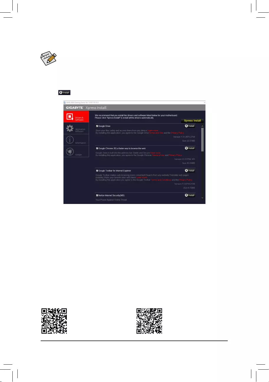
«XpressInstall»willautomaticallyscanyoursystemandthenlistallofthedriversthatarerecommendedto
install. You can click the Xpress Installbuttonand«XpressInstall»willinstallalloftheselecteddrivers.Orclick
the arrow icon to individually install the drivers you need.
— 37 —

Regulatory Statements
Regulatory Notices
This document must not be copied without our written permission, and the contents there of must not be imparted
toathirdpartynorbeusedforanyunauthorizedpurpose.
Contraventionwillbeprosecuted.Webelievethattheinformationcontainedhereinwasaccurateinallrespects
at the time of printing. GIGABYTE cannot, however, assume any responsibility for errors or omissions in this text.
Also note that the information in this document is subject to change without notice and should not be construed
as a commitment by GIGABYTE.
Our Commitment to Preserving the Environment
Inaddition to high-efciency performance, all GIGABYTE motherboards fulll European Union regulations
forRoHS(RestrictionofCertainHazardousSubstancesinElectricalandElectronicEquipment)andWEEE
(WasteElectricalandElectronicEquipment)environmentaldirectives,aswellasmostmajorworldwidesafety
requirements.Topreventreleasesofharmfulsubstancesintotheenvironmentandtomaximizetheuseofour
natural resources, GIGABYTE provides the following information on how you can responsibly recycle or reuse
mostofthematerialsinyour»endoflife»product.
Restriction of Hazardous Substances (RoHS) Directive Statement
GIGABYTEproductshavenotintendedtoaddandsafefromhazardoussubstances(Cd,Pb,Hg,Cr+6,PBDE
andPBB).ThepartsandcomponentshavebeencarefullyselectedtomeetRoHSrequirement.Moreover,weat
GIGABYTE are continuing our efforts to develop products that do not use internationally banned toxic chemicals.
Waste Electrical & Electronic Equipment (WEEE) Directive Statement
GIGABYTEwillfulllthenationallawsasinterpretedfromthe2002/96/ECWEEE(WasteElectricalandElectronic
Equipment)directive.TheWEEEDirectivespeciesthetreatment,collection,recyclinganddisposalofelectric
andelectronicdevicesandtheircomponents.UndertheDirective,usedequipmentmustbemarked,collected
separately, and disposed of properly.
WEEE Symbol Statement
The symbol shown below is on the product or on its packaging, which indicates that this product
must not be disposed of with other waste. Instead, the device should be taken to the waste collection
centers for activation of the treatment, collection, recycling and disposal procedure. The separate
collection and recycling of your waste equipment at the time of disposal will help to conserve natural
resources and ensure that it is recycled in a manner that protects human health and the environment.
For more information about where you can drop off your waste equipment for recycling, please contact your
localgovernmentofce,yourhouseholdwastedisposalserviceorwhereyoupurchasedtheproductfordetails
of environmentally safe recycling.
Whenyourelectricalorelectronicequipmentisnolongerusefultoyou,«takeitback»toyourlocalorregional
waste collection administration for recycling.
Ifyouneedfurtherassistanceinrecycling,reusinginyour«endoflife»product,youmaycontactusatthe
Customer Care number listed in your product’s user’s manual and we will be glad to help you with your effort.
Finally, we suggest that you practice other environmentally friendly actions by understanding and using the
energy-savingfeaturesofthisproduct(whereapplicable),recyclingtheinnerandouterpackaging(including
shippingcontainers)thisproductwasdeliveredin,andbydisposingoforrecyclingusedbatteriesproperly.
Withyourhelp,wecanreducetheamountofnaturalresourcesneededtoproduceelectricalandelectronic
equipment,minimizetheuseoflandllsforthedisposalof«endoflife»products,andgenerallyimproveour
qualityoflifebyensuringthatpotentiallyhazardoussubstancesarenotreleasedintotheenvironmentandare
disposed of properly.
— 38 —

FCC Notice (U.S.A. Only)
This equipment has been tested and found to comply with the limits for a Class B digital device, pursuant to Part
15oftheFCCRules.Theselimitsaredesignedtoprovidereasonableprotectionagainstharmfulinterference
in a residential installation. This equipment generates, uses, and can radiate radio frequency energy and, if not
installed and used in accordance with the instructions, may cause harmful interference to radio communications.
However, there is no guarantee that interference will not occur in a particular installation. If this equipment does
cause harmful interference to radio or television reception, which can be determined by turning the equipment
off and on, the user is encouraged to try to correct the interference by one or more of the following measures:
Reorientorrelocatethereceivingantenna.
Increase the separation between the equipment and receiver.
Connect the equipment into an outlet on a circuit different from that to which the receiver is connected.
Consult a dealer or experienced TV/radio technician for help.
Canada, Industry Canada (IC) Notices / Canada, avis d‘Industry Canada (IC)
ThisClassBdigitalapparatuscomplieswithCanadianICES-003andRSS-210.
Operationissubjecttothefollowingtwoconditions:(1)thisdevicemaynotcauseinterference,and(2)this
device must accept any interference, including interference that may cause undesired operation of the device.
CetappareilnumériquedeclasseBestconformeauxnormescanadiennesICES-003etRSS-210.
Sonfonctionnement est soumis aux deux conditions suivantes: (1)cet appareilne doit pas causer
d’interférenceet(2)cetappareildoitacceptertouteinterférence,notammentlesinterférencesquipeuvent
affecter son fonctionnement.
— 39 —
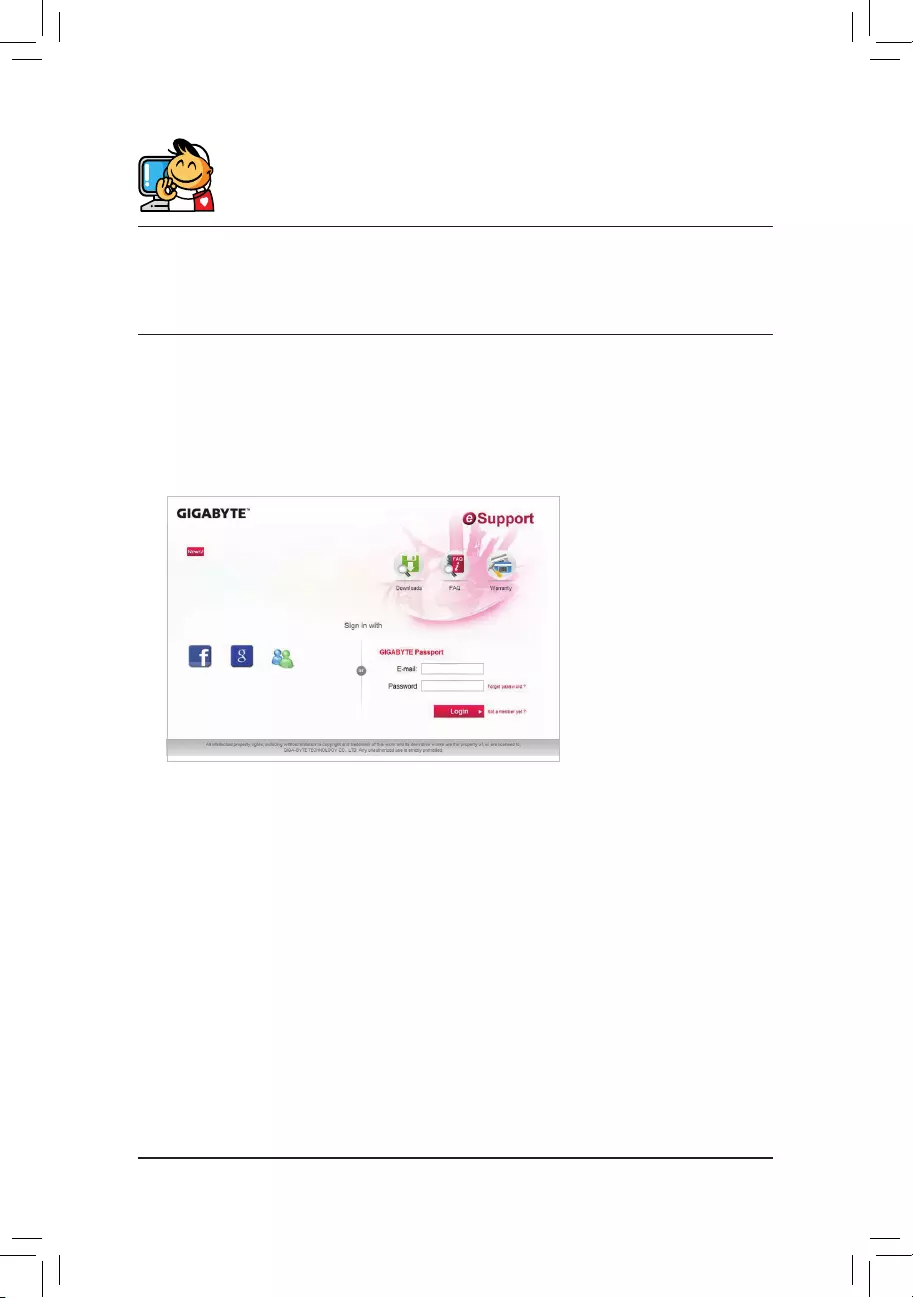
Contact Us
GIGA-BYTE TECHNOLOGY CO., LTD.
Address:No.6,BaoqiangRd.,XindianDist.,NewTaipeiCity231,Taiwan
TEL: +886-2-8912-4000, FAX: +886-2-8912-4005
Tech.andNon-Tech.Support(Sales/Marketing):http://esupport.gigabyte.com
WEBaddress(English):http://www.gigabyte.com
WEBaddress(Chinese):http://www.gigabyte.tw
•GIGABYTE eSupport
Tosubmitatechnicalornon-technical(Sales/Marketing)question,pleaselinkto:
http://esupport.gigabyte.com
— 40 —
Manual
View the manual for the Gigabyte GA-AB350-Gaming 3 here, for free. This user manual comes under the category motherboards and has been rated by 1 people with an average of a 9.3. This manual is available in the following languages: English. Do you have a question about the Gigabyte GA-AB350-Gaming 3?
Ask your question here
Gigabyte GA-AB350-Gaming 3 specifications
Below you will find the product specifications and the manual specifications of the Gigabyte GA-AB350-Gaming 3.
Supported memory types
DDR4-SDRAM
Processor manufacturer
AMD
ATX Power connector (24-pin)
Yes
Number of M.2 (M) slots
1
General
| Brand | Gigabyte |
| Model | GA-AB350-Gaming 3 | GA-AB350-GAMING 3 |
| Product | motherboard |
| EAN | 0889523009093, 4719331801281, 4719331801359, 889523009093, 0889523009314, 4571486461907 |
| Language | English |
| Filetype | User manual (PDF), Installation Guide (PDF) |
Memory
| Supported memory types | DDR4-SDRAM |
| Memory slots type | DIMM |
| Number of memory slots | 4 |
| Memory channels | Dual-channel |
| Unbuffered memory | Yes |
| Supported memory clock speeds | 2133,2400,2933,3200 MHz |
| Supported memory module capacities | 4GB, 8GB, 16GB |
| Maximum internal memory | 64 GB |
Processor
| Processor manufacturer | AMD |
| Compatible processor series | AMD A, AMD Athlon, AMD Athlon X4, AMD Ryzen 3, AMD Ryzen 3 2nd Gen, AMD Ryzen 3 3rd Gen, AMD Ryzen 5, AMD Ryzen 5 2nd Gen, AMD Ryzen 5 3rd Gen, AMD Ryzen 7, AMD Ryzen 7 2nd Gen, AMD Ryzen 7 3rd Gen, AMD Ryzen 9 3rd Gen |
| Processor socket | Socket AM4 |
Internal I/O
| ATX Power connector (24-pin) | Yes |
| EPS power connector (8-pin) | Yes |
| Number of SATA II connectors | 0 |
| Number of SATA III connectors | 6 |
| CPU fan connector | Yes |
| Number of chassis fan connectors | 2 |
| Front panel audio connector | Yes |
| Number of Parallel ATA connectors | 0 |
| Front panel connector | Yes |
| S/PDIF out connector | Yes |
| USB 2.0 connectors | 2 |
| USB 3.2 Gen 1 (3.1 Gen 1) connectors | 1 |
| USB 3.2 Gen 2 (3.1 Gen 2) connectors | 0 |
| TPM connector | Yes |
Expansion slots
| Number of M.2 (M) slots | 1 |
| PCI Express x16 slots | 3 |
| PCI Express x1 slots | 2 |
BIOS
| Clear CMOS jumper | Yes |
| BIOS type | UEFI AMI |
| BIOS memory size | 16 Mbit |
| ACPI version | 5.0 |
Rear panel I/O ports
| PS/2 ports quantity | 1 |
| HDMI ports quantity | 1 |
| USB 3.2 Gen 2 (3.1 Gen 2) Type-C ports quantity | 0 |
| USB 3.2 Gen 2 (3.1 Gen 2) Type-A ports quantity | 2 |
| USB 3.2 Gen 1 (3.1 Gen 1) Type-A ports quantity | 4 |
| USB 3.2 Gen 1 (3.1 Gen 1) Type-C ports quantity | 0 |
| Ethernet LAN (RJ-45) ports | 1 |
| USB 2.0 ports quantity | 1 |
| Headphone outputs | 1 |
| Microphone in | Yes |
| S/PDIF out port | Yes |
| Firewire (IEEE 1394) ports | 0 |
| VGA (D-Sub) ports quantity | 0 |
| DVI-D ports quantity | 1 |
| eSATA ports quantity | 0 |
Network
Features
| Component for | PC |
| Motherboard chipset family | AMD |
| Linux operating systems supported | Yes |
| Windows operating systems supported | Yes |
| Motherboard chipset | AMD B350 |
| Motherboard form factor | ATX |
| Audio output channels | 7.1 channels |
| Power source type | ATX |
Storage controllers
| Supported storage drive types | HDD & SSD |
| RAID levels | 0, 1,10 |
Weight & dimensions
show more
Frequently asked questions
Can’t find the answer to your question in the manual? You may find the answer to your question in the FAQs about the Gigabyte GA-AB350-Gaming 3 below.
What is the width of the Gigabyte GA-AB350-Gaming 3?
The Gigabyte GA-AB350-Gaming 3 has a width of 230 mm.
What is the depth of the Gigabyte GA-AB350-Gaming 3?
The Gigabyte GA-AB350-Gaming 3 has a depth of 305 mm.
Is the manual of the Gigabyte GA-AB350-Gaming 3 available in English?
Yes, the manual of the Gigabyte GA-AB350-Gaming 3 is available in English .
Is your question not listed? Ask your question here
Gigabyte
Loading…
G
- GA-970A-DS3P FX V2.1
- GA-970A-DS3P rev.2.1
- GA-970A-UD311
- GA-970A-UD3P6
- GA-990FX
- GA-990FXA-D35
- GA-990FXA-UD315
- GA-990FXA-UD3 R53
- GA-990FXA-UD3 ULTRA
- GA-990FXA-UD510
- GA-990FXA-UD5 R53
- GA-990FXA-UD76
- GA-990FX-GAMING
- GA-990XA-UD310
- GA-990XA-UD3 R53
- GA-990X-GAMING SLI
- GA-9ILDR2
- GA-9ILDTH3
- GA-9ITDW2
- GA-9ITDW-CN
- GA-9IVDPC
- GA-9IVDP-GG
- GA-9IVDPH
- GA-9IVDPL
- GA-9IVDPP-GG
- GA-9IVDT
- GA-9IVDTH2
- GA-9IVDTH1-HT
- GA-9IVDTH3-HT
- GA-9SISL
- GA-A320M-H3
- GA-A320M-HD2
- GA-A320M-S2H3
- GA-A320M-S2H V2
- GA-A55-DS3P3
- GA-A55M-DS214
- GA-A55M-S2H7
- GA-A55M-S2HP4
- GA-A55M-S2V7
- GA-A55M-S3P
- GA-A55-S3P5
- GA-A75-D3H5
- GA-A75-DS3P5
- GA-A75M-D2H7
- GA-A75M-DS28
- GA-A75M-S2V5
- GA-A75M-UD2H5
- GA-A75N-USB34
- GA-A75-UD4H5
- GA-AB350
- GA-AB350-Gaming2
- GA-AB350 GAMING 32
- GA-AB350M-DS2
- GA-AB350M-DS3H
- GA-AB350M-DS3H V2
- GA-AM1M-S2H3
- GA-AM1M-S2P3
- GA-AURORA-RH
- GA-AX370-Gaming2
- GA-AX370-Gaming 3
- GA-AX370 GAMING 53
- GA-AX370 GAMING K32
- GA-AX370 GAMING K73
- GA-B150-HD3 DDR3
- GA-B150-HD3 DDR3-WP
- GA-B150-HD3P2
- GA-B150M-D2V3
- GA-B150M-D2V DDR33
- GA-B150M-D2VX-SI
- GA-B150M-D3H2
- GA-B150M D3H-DDR32
- GA-B150M-D3H-GSM
- GA-B150M-D3P
- GA-B150M-D3V4
- GA-B150M-D3V DDR32
- GA-B150M-D3VX-SI2
- GA-B150M-DASH2
- GA-B150M-DS3H DDR3
- GA-B150M-Gaming3
- GA-B150M-HD3
- GA-B150M-PIO-SI
- GA-B150M-Power2-EC
- GA-B150M-SC-SI
- GA-B150M-SE-SI
- GA-B150N
- GA-B150N-GSM2
- GA-B250-FINTECH
- GA-B250-HD32
- GA-B250-HD3P
- GA-B250M-D2V2
- GA-B250M-D2VX-SI
- GA-B250M-D3H
- GA-B250M-D3P
- GA-B250M-D3VX-SI2
- GA-B250M-DS3H2
- GA-B250M-EVO
- GA-B250M-Gaming
- GA-B250M-Power2
- GA-B250M-Wind
- GA-B350M-D2
Loading…
Loading…
Nothing found
GA-AB350 GAMING 3
R101 Schematics
37 pgs1.42 Mb0
User Manual
40 pgs12.3 Mb1
Table of contents
Loading…
…
Gigabyte User Manual
Specifications and Main Features
Frequently Asked Questions
User Manual

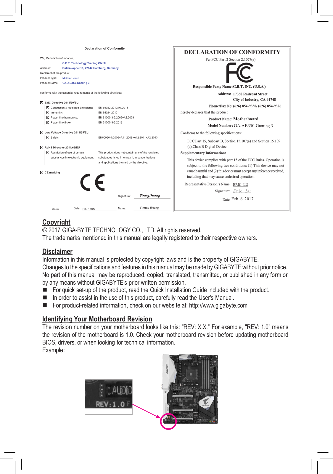
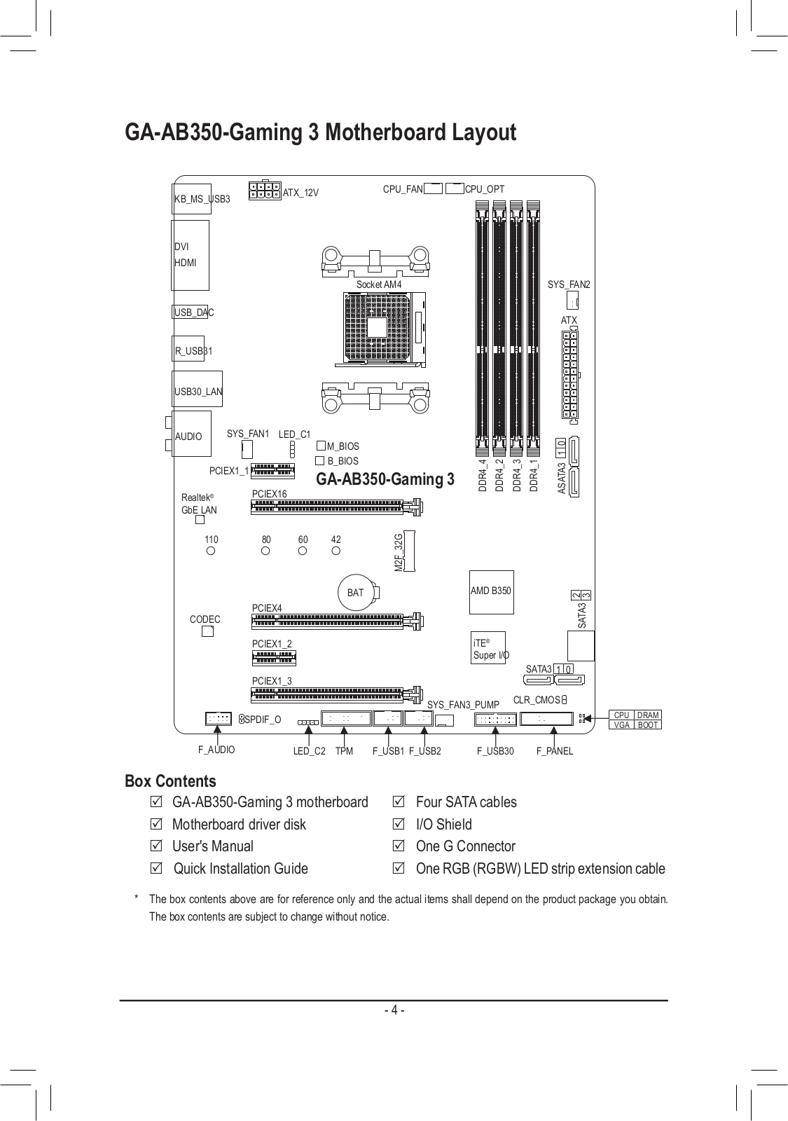
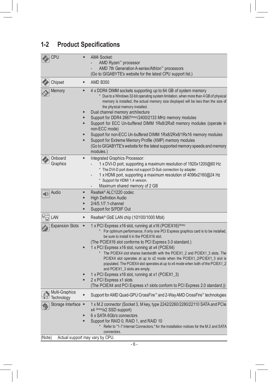
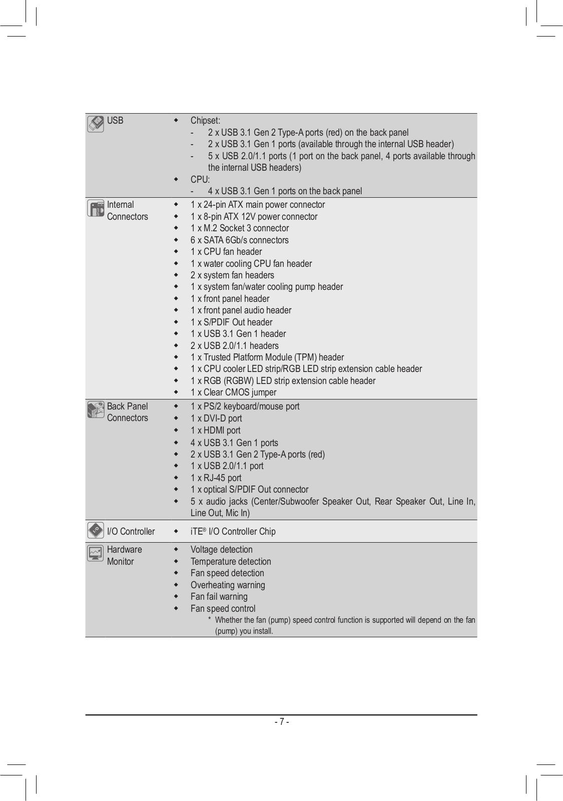
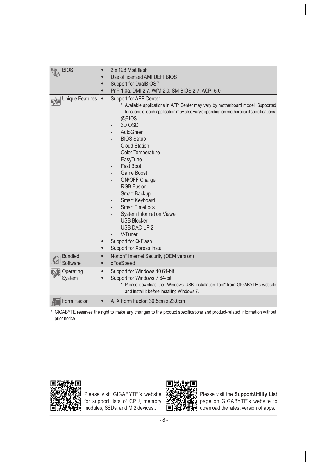
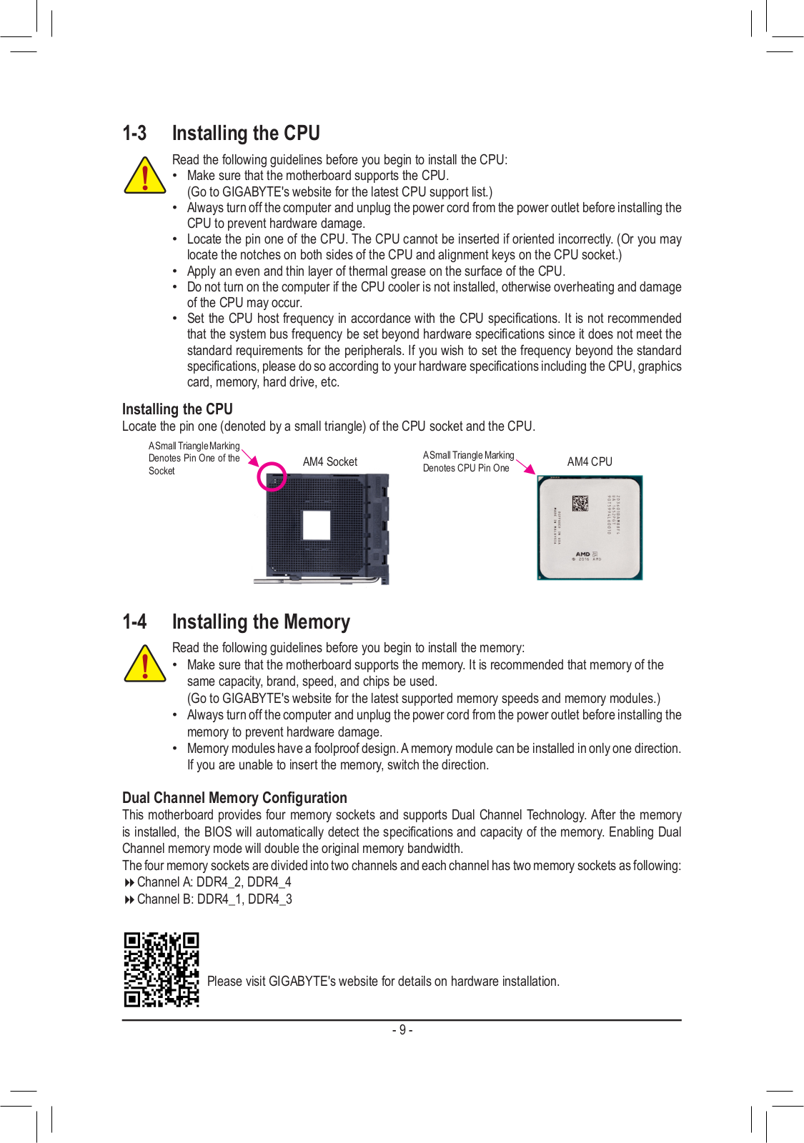
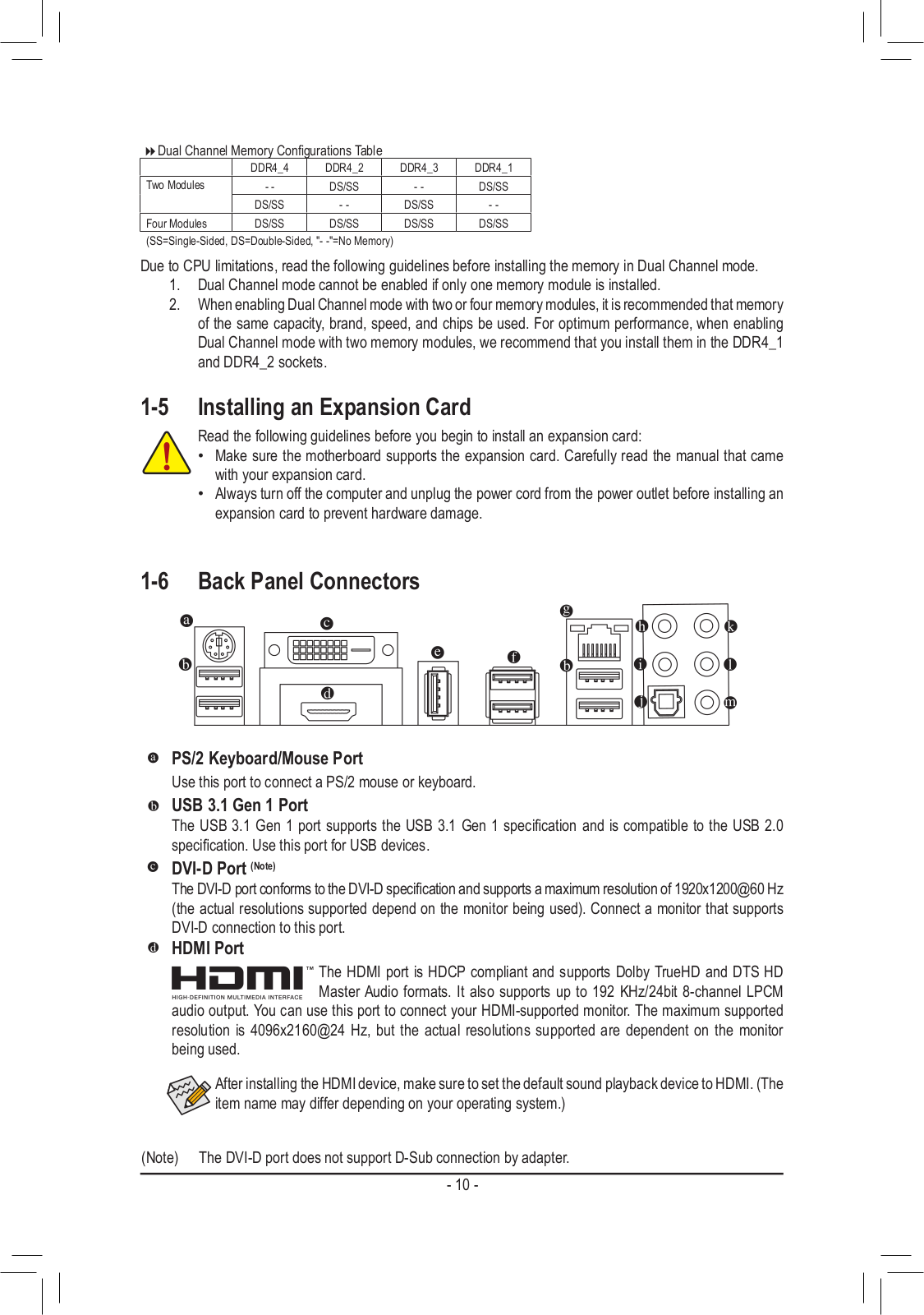
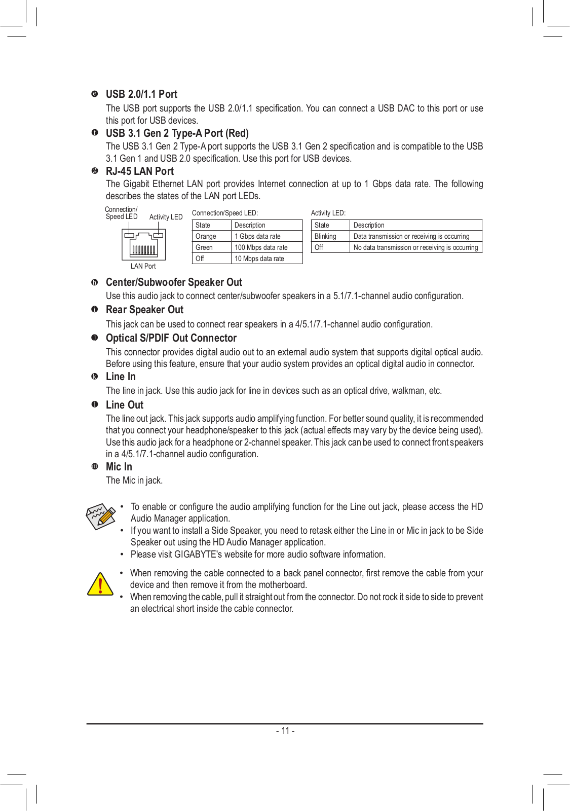
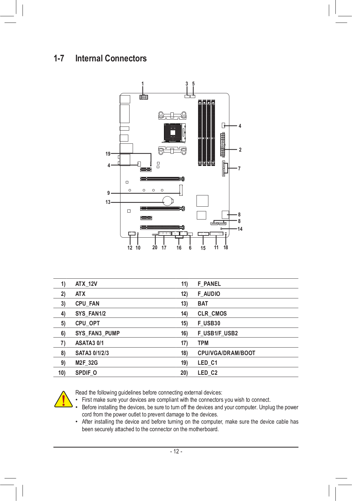
Loading…
+ 28 hidden pages
You need points to download manuals.
1 point = 1 manual.
You can buy points or you can get point for every manual you upload.
Buy points
Upload your manuals
Gigabyte AB350 Gaming 3
To reduce the impacts on global warming, the packaging materials of this product
are recyclable and reusable. GIGABYTE works with you to protect the environment.
For more product details, please visit GIGABYTE’s website.
User’s Manual
Rev. 1002
12ME-AB35GM3-1002R
User manual
View the manual for the Gigabyte AB350 Gaming 3 here, for free. This manual comes under the category motherboards and has been rated by 1 people with an average of a 7.8. This manual is available in the following languages: English. Do you have a question about the Gigabyte AB350 Gaming 3 or do you need help?
Ask your question here
Index
- GA-AB350-Gaming 3 Motherboard Layout
- Chapter 1 Hardware Installation
- Chapter 2 BIOS Setup
- Chapter 3 Appendix
Product Images (2)

Gigabyte AB350 Gaming 3 specifications
Below you will find the product specifications and the manual specifications of the Gigabyte AB350 Gaming 3.
The Gigabyte AB350 Gaming 3 is a motherboard designed for gaming enthusiasts. It is compatible with AMD Ryzen processors and supports DDR4 memory. The ATX form factor motherboard features an AM4 socket and the AMD B350 chipset.
The Gigabyte AB350 Gaming 3 offers a range of connectivity options, including USB 3.1, USB-C, HDMI, DVI, and DisplayPort. It also has multiple PCIe slots for graphics cards and other expansion cards, as well as M.2 slots for high-speed storage.
In terms of audio, the motherboard features built-in Realtek ALC1220 audio with high-quality capacitors for an immersive gaming experience. It also has RGB lighting zones for customising the look of the gaming setup.
Overall, the Gigabyte AB350 Gaming 3 is a feature-rich motherboard that is designed to meet the needs of gamers who require high performance and reliability.
General
Frequently Asked Questions
Can’t find the answer to your question in the manual? You may find the answer to your question in the FAQs about the Gigabyte AB350 Gaming 3 below.
How can I properly install the Gigabyte AB350 Gaming 3 motherboard into my computer case?
Before installing the motherboard, ensure that your computer case is compatible with the ATX form factor and that all necessary standoffs are correctly positioned. Align the screw holes on the motherboard with the standoffs, and secure it using screws. Connect all required power and data cables.
How do I connect the front panel cables to the motherboard?
Locate the front panel header on the motherboard, typically located near the bottom edge. Refer to the motherboard manual for the pinout diagram, and carefully connect the front panel cables according to the labels for power switch, power LED, HDD LED, and reset switch.
What BIOS settings should I configure for optimal performance? The translation goes here
Access the BIOS by pressing the designated key during the boot process (usually Del or F2). Refer to the motherboard manual for specific options and settings. Some important settings to consider include enabling XMP for memory overclocking, adjusting fan curves for optimal cooling, and selecting the appropriate boot order.
How do I install and configure my {motherboard} Gigabyte AB350 Gaming 3?
Connect your storage devices to the appropriate SATA ports on the motherboard using SATA cables. Ensure that the drives are properly powered. To configure your storage, access the BIOS and navigate to the storage settings. Here, you can select the boot device priority, enable RAID configurations, or adjust settings specific to your storage needs.
How can I update the BIOS on my Gigabyte AB350 Gaming 3 motherboard?
Download the latest BIOS version from the official Gigabyte website and save it to a USB flash drive. Restart your computer and enter the BIOS. Navigate to the BIOS update utility, usually found under the ‘Tools’ or ‘Settings’ section. Select the USB drive containing the BIOS update file and follow the on-screen instructions to complete the update process.
Is the manual of the Gigabyte AB350 Gaming 3 available in English?
Yes, the manual of the Gigabyte AB350 Gaming 3 is available in English .
Is your question not listed? Ask your question here
Free Manuals for Gigabyte GA-AB350-Gaming 3 (rev. 1.x)
Manufacturer:Gigabyte
Category:Computers & Peripherals
Device:Gigabyte GA-AB350-Gaming 3 (rev. 1.x)
Name:Multilingual Installation Guide
Language:العربيةБългарскиČeštinaDeutschΕλληνικάEnglishEspañolفارسىFrançaisעבריתHrvatskiMagyarBahasa IndonesiaItaliano日本語한국어PolskiPortuguêsRomânăРусскийSrpskiไทยTürkçeTiếng Việt中文
Version:103
Pages:2
Size:9.03 MB
DescriptionGigabyte GA-AB350-Gaming 3 (rev. 1.x) Multilingual Installation GuideView Gigabyte GA-AB350-Gaming 3 (rev. 1.x) Multilingual Installation Guide 103 (العربية, Български, Čeština, Deutsch, Ελληνικά, English, Español, فارسى, Français, עברית, Hrvatski, Magyar, Bahasa Indonesia, Italiano, 日本語, 한국어, Polski, Português, Română, Русский, Srpski, ไทย, Türkçe, Tiếng Việt, 中文)
Manufacturer:Gigabyte
Category:Computers & Peripherals
Device:Gigabyte GA-AB350-Gaming 3 (rev. 1.x)
Name:Multilingual Installation Guide
Language:العربيةБългарскиČeštinaDeutschΕλληνικάEnglishEspañolفارسىFrançaisעבריתHrvatskiMagyarBahasa IndonesiaItaliano日本語한국어PolskiPortuguêsRomânăРусскийSrpskiไทยTürkçeTiếng Việt中文
Version:102
Pages:2
Size:8.98 MB
DescriptionGigabyte GA-AB350-Gaming 3 (rev. 1.x) Multilingual Installation GuideView Gigabyte GA-AB350-Gaming 3 (rev. 1.x) Multilingual Installation Guide 102 (العربية, Български, Čeština, Deutsch, Ελληνικά, English, Español, فارسى, Français, עברית, Hrvatski, Magyar, Bahasa Indonesia, Italiano, 日本語, 한국어, Polski, Português, Română, Русский, Srpski, ไทย, Türkçe, Tiếng Việt, 中文)
Manufacturer:Gigabyte
Category:Computers & Peripherals
Device:Gigabyte GA-AB350-Gaming 3 (rev. 1.x)
Name:Manual
Language:中文中文(简体)
Version:1003
Pages:40
Size:12.49 MB
Manufacturer:Gigabyte
Category:Computers & Peripherals
Device:Gigabyte GA-AB350-Gaming 3 (rev. 1.x)
Name:Manual
Language:한국어
Version:1002
Pages:40
Size:11.73 MB
Manufacturer:Gigabyte
Category:Computers & Peripherals
Device:Gigabyte GA-AB350-Gaming 3 (rev. 1.x)
Name:Manual
Language:日本語
Version:1002
Pages:40
Size:11.89 MB
Manufacturer:Gigabyte
Category:Computers & Peripherals
Device:Gigabyte GA-AB350-Gaming 3 (rev. 1.x)
Name:Manual
Language:English
Version:1002
Pages:40
Size:11.73 MB
Manufacturer:Gigabyte
Category:Computers & Peripherals
Device:Gigabyte GA-AB350-Gaming 3 (rev. 1.x)
Name:Manual
Language:中文中文(繁體)
Version:1002
Pages:44
Size:12.62 MB